Surface-mounted or wall-mounted luminaire

a technology of surface-mounted or wall-mounted luminaires and luminaires, which is applied in the direction of fixed installation, lighting and heating equipment, lighting support devices, etc., can solve the problems of difficult to achieve optimal workplace and space illumination, and achieve good space illumination

Inactive Publication Date: 2011-12-22
HERBERT WALDMANN GMBH & CO KG
View PDF4 Cites 5 Cited by
  • Summary
  • Abstract
  • Description
  • Claims
  • Application Information

AI Technical Summary

Benefits of technology

[0010]The proposed invention provides an elongate light fixture having a substantially triangular cross-section. The light fixture is screwed to a supply duct with the rear wall thereof A front rail runs parallel to the rear wall. Transparent panels and are inserted detachably between the rear wall and rail. In the interior of the light fixture, a fluorescent lamp is provided as the luminous element. The light emitted by said fluorescent lamp is reflected upward by way of reflector surfaces that open in the shape of a funnel and is scattered diffusely in the direction A by means of the frosted panel. The panel surfaces, which likewise open in the shape of a funnel, reflect the light exiting downward from the lamp in the direction toward the panel, the grooved structure of which ensures that the light is deflected substantially in the direction B, while the portion of the side light exiting in the direction C is reduced. With this reflector and panel configuration, firstly good illumination of the space and secondly specific and glare-free workplace lighting is made possible.
[0011]An aspect of the present invention is to provide a luminaire that significantly improves the quality of the directly and indirectly emitted light. This is achieved, for one, by a particular reflector geometry, which ensures the emission of extremely homogeneous light both upward and downward relative to a fixed position, and secondly by the configuration of the screens which cover the luminaire toward the top and the bottom and by which the light is scattered diffusely upward and the light is oriented downward such that the portion of horizontally exiting light is as low as possible.
[0012]It is another aspect of the proposed invention that reflector configurations are provided which both favor the light direction described and are economical to produce and install.
[0014]It is another aspect of the proposed invention that the resultant unit is easy production and improves the service friendliness, while offering safe handling for installers.
[0018]Another aspect of the present invention provides a luminaire element that is not only easy to orient in series, but also is easy to install and remove.

Problems solved by technology

Based upon this reference it is difficult to achieve an optimal workplace and space illumination while also being both easy to install and highly service-friendly.

Method used


Image

  • Surface-mounted or wall-mounted luminaire
  • Surface-mounted or wall-mounted luminaire
  • Surface-mounted or wall-mounted luminaire

Examples


Embodiment Construction

[0031]Reference will now be made in detail to several embodiments of the invention that are illustrated in the accompanying drawings. Wherever possible, same or similar reference numerals are used in the drawings and the description to refer to the same or like parts or steps. The drawings are in simplified form and are not to precise scale. For purposes of convenience and clarity only, directional terms, such as top, bottom, up, down, over, above, and below may be used with respect to the drawings. These and similar directional terms should not be construed to limit the scope of the invention in any manner. The words “connect,”“couple,” and similar terms with their inflectional morphemes do not necessarily denote direct and immediate connections, but also include connections through mediate elements or devices.

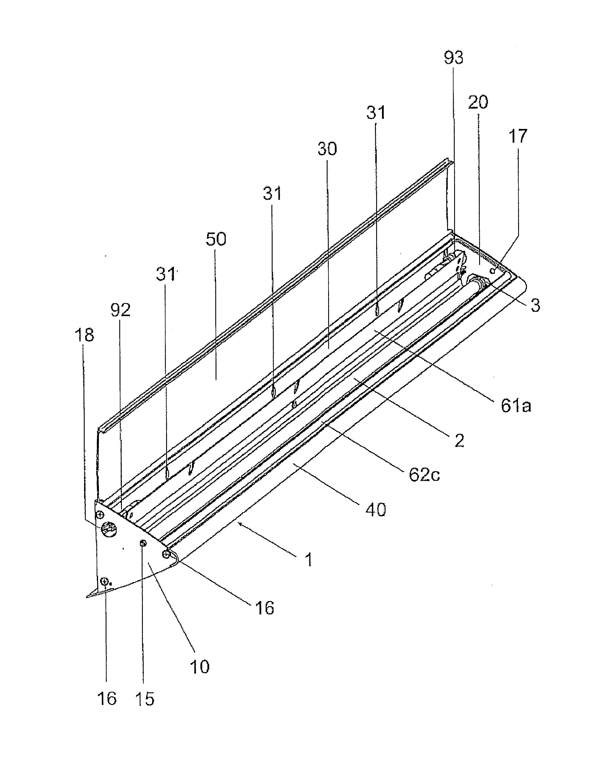
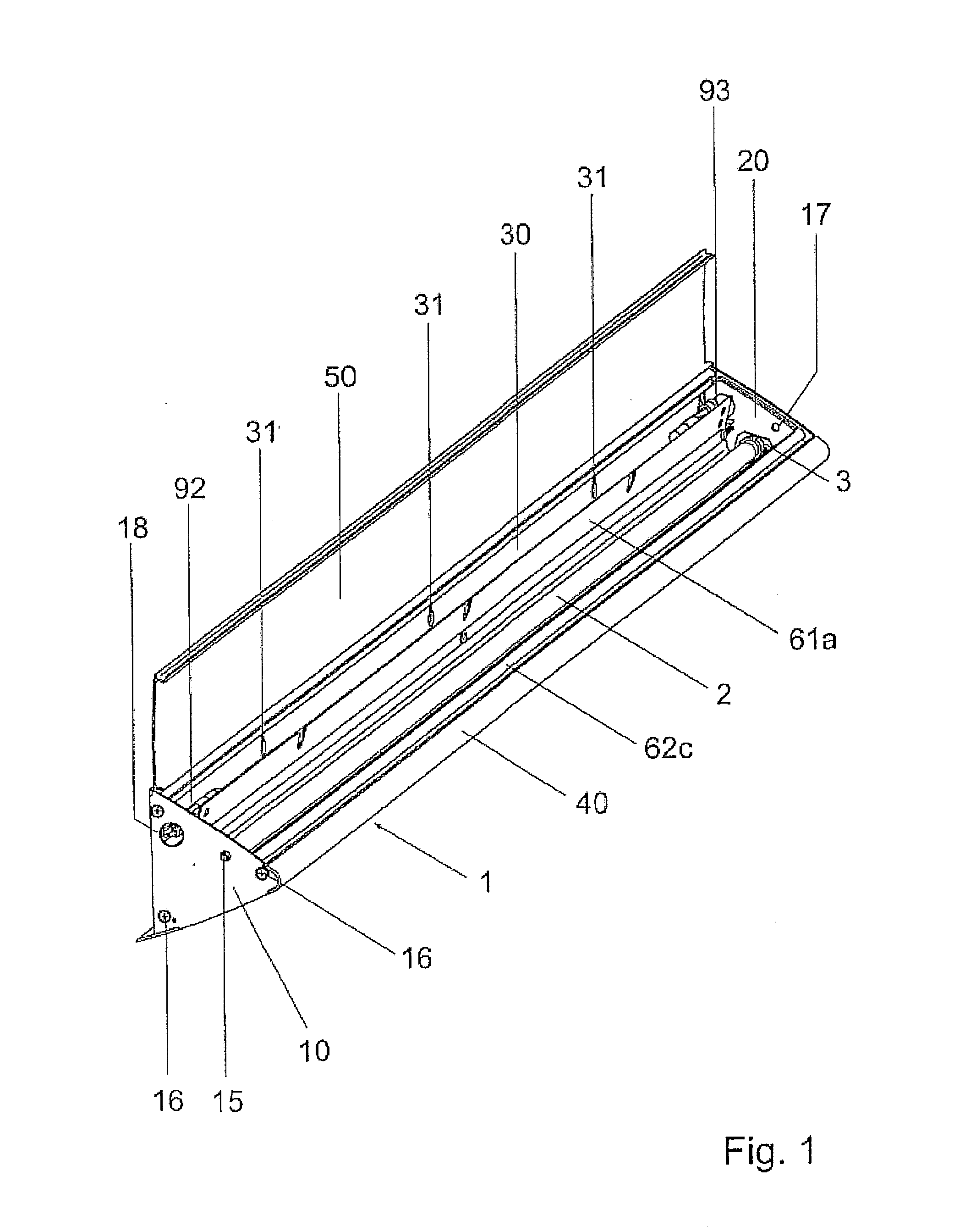
[0032]The luminaire housing is substantially composed of a rear wall 30, to which lateral parts 10 and 20 are screwed perpendicularly by countersunk head screws 16, the later...


PUM


Abstract

The invention relates to an elongate light fixture having a substantially triangular cross-section. The light fixture is screwed to a supply duct with the rear wall thereof. A front rail runs parallel to the rear wall. Transparent panels and are inserted detachably between the rear wall and rail. In the interior of the light fixture, a fluorescent lamp is provided as the luminous element. The light emitted by said fluorescent lamp is reflected upward by way of reflector surfaces that open in the shape of a funnel and is scattered diffusely in the direction A by means of the frosted panel. The panel surfaces, which likewise open in the shape of a funnel, reflect the light exiting downward from the lamp in the direction toward the panel, the grooved structure of which ensures that the light is deflected substantially in the direction B, while the portion of the side light exiting in the direction C is reduced. With this reflector and panel configuration, firstly good illumination of the space and secondly specific and glare-free workplace lighting is made possible.

Description

CROSS REFERENCE TO RELATED APPLICATIONS[0001]This application claims priority from PCT Patent Application Ser. No. PCT / EP2009 / 007770, filed Oct. 29, 2009, the entire contents of which is herein incorporated fully by reference, which in turn claims priority form German Patent Application Serial No. 10 2009 007 308.6 filed Aug. 3, 2009.FIGURE FOR PUBLICATION[0002]FIG. 2BACKGROUND OF THE INVENTION[0003]1. Field of the Invention[0004]The present invention relates to a surface-mounted or wall-mounted luminaire with improved reflection. More particularly, the present invention relates to an elongate light fixture having a substantially triangular cross-section with a particular construction substantially enhancing direct and reflected light and which is operably useful in installation.[0005]2. Description of the Related Art[0006]The related art involves surface-mounted luminaries substantially composed of an elongated housing having an approximately triangular cross-section, the back wall...

Claims


Application Information

Patent Timeline
Patent Type & Authority Applications(United States)
IPC IPC(8): F21V7/06
CPCF21S4/003F21S8/031F21S8/033F21V3/00F21V7/0016F21V7/0025F21Y2103/00F21V15/015F21V17/107F21V17/164F21V21/005F21V21/02F21V7/005F21S4/20
Inventor EBERHARDT, MARCUS
Owner HERBERT WALDMANN GMBH & CO KG
Why Eureka
Try Eureka