
Interior lamp

a technology for interior lighting and lamps, applied in interior lighting, transportation and packaging, lighting and heating equipment, etc., can solve the problems of reflection loss, deterioration of light utilization efficiency, lack of merchandizability, etc., and achieve the effect of superior illumination function and illumination effect, and high merchandizability

Inactive Publication Date: 2011-06-07
STANLEY ELECTRIC CO LTD
View PDF7 Cites 5 Cited by
  • Summary
  • Abstract
  • Description
  • Claims
  • Application Information

AI Technical Summary

Benefits of technology

The present invention provides an interior lamp that can radiate light with a mixed color of white and colored light, and can illuminate a vehicle compartment with brighter white light than colored light. The lamp has excellent illumination function and effect, and high merchandizability. The interior lamp includes an LED light source unit and a light illumination unit, which can control the white and colored light emitted from the LED lamps to radiate the light to the outside. The light illumination unit includes a light diffusion layer and a light transmission layer, which can be positioned to control the light emitted from the LED lamps. The interior lamp can provide both spot light and soft light depending on the needs.

Problems solved by technology

With this illumination light, certain illumination effects (providing comfortable environment, etc.) cannot be achieved sufficiently, resulting in lack of merchandizability.
Accordingly, as in the case disclosed in Japanese Patent Application Laid-Open No. Hei. 10-194041, the interior lamp disclosed in Japanese Patent Application Laid-Open No. 2003-127769 results in insufficient merchandizability.
Accordingly, in this case the reflection loss may deteriorate light utilization efficiency.
Namely, there is a problem in which the light intensity may be reduced.

Method used


Image

  • Interior lamp
  • Interior lamp
  • Interior lamp

Examples


Embodiment Construction

Hereinafter, a description will be given of several exemplary embodiments with reference to FIG. 1 through FIG. 10. In the shown exemplary embodiments, the same or similar parts are denoted by the same reference numerals / symbols.

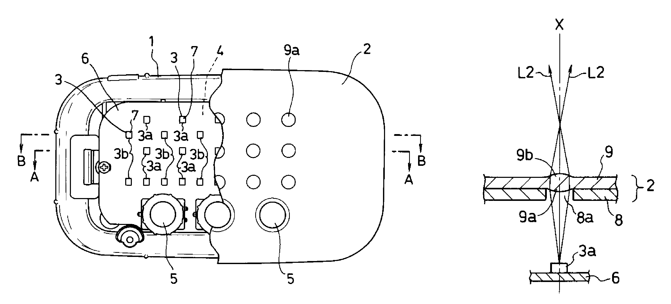
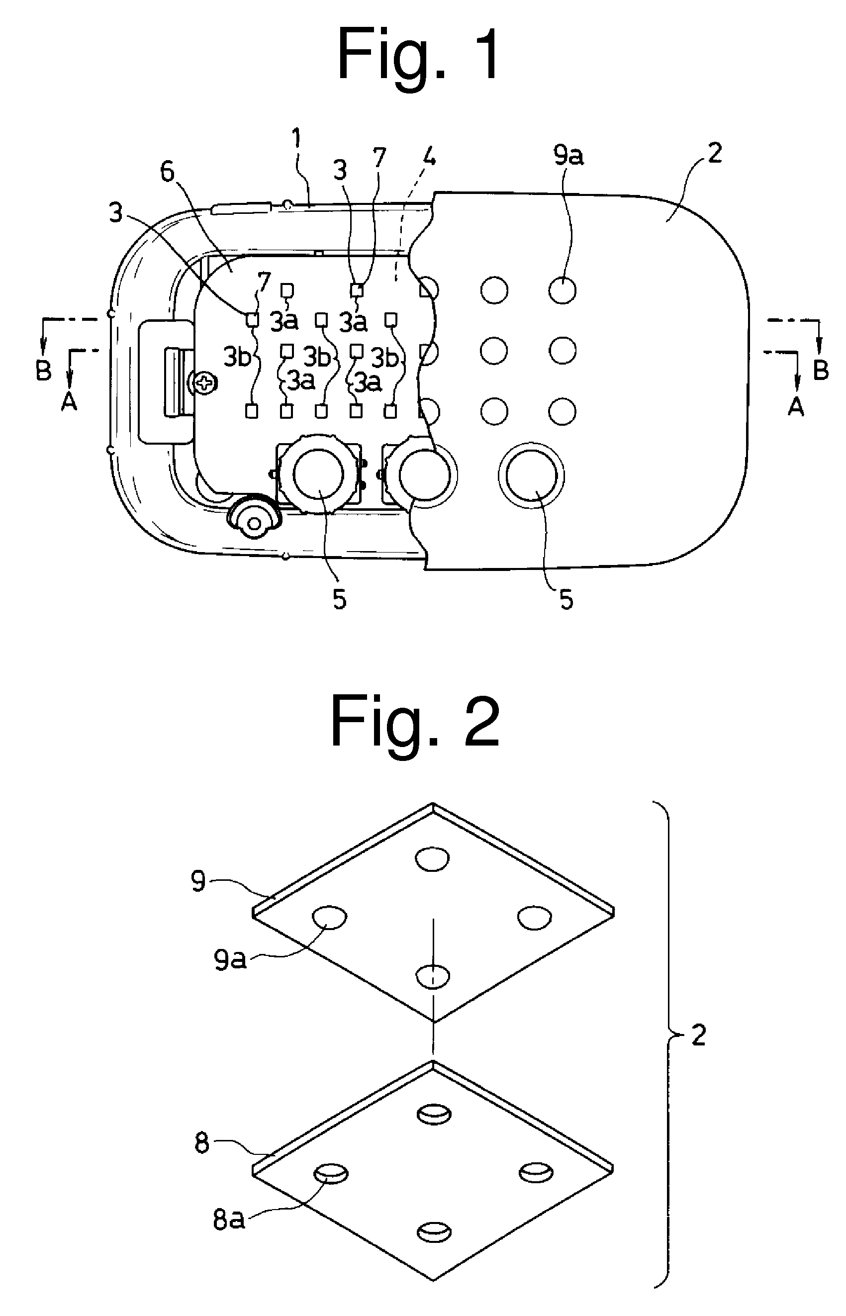
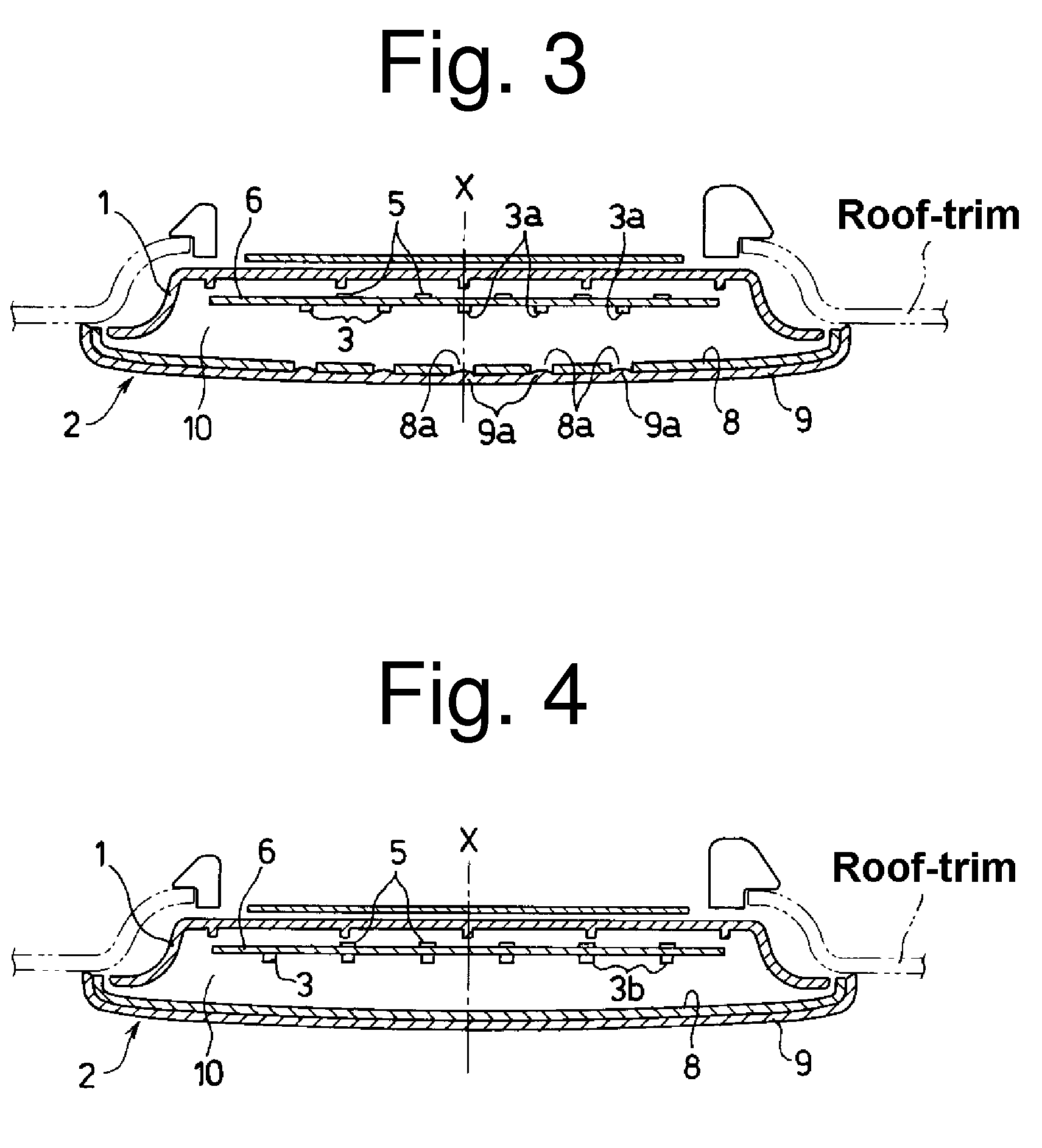
FIG. 1 is a plan view, part of which is cut away, showing one exemplary embodiment of an interior lamp made in accordance with the principles of the presently disclosed subject matter. The interior lamp can include a housing case 1, a cover case 2 serving as a light illumination unit, and a part mounting substrate 6 serving as an LED light source unit. The part mounting substrate 6 can include LED lamps 3 as light sources, electronic components 4 (not shown, such as resistors), and operation components 5 (such as switches) which are mounted thereon. The housing case 1 and the cover case 2 can form a closed space serving as a lighting chamber 10. In this closed space, the part mounting substrate 6 can be securely supported while the light emitting surface 7 o...


PUM


Abstract

An interior lamp can achieve both an excellent illumination function and an excellent illumination effect (providing a comfortable environment) and may possibly provide high merchandizability characteristics. The interior lamp can include an LED light source unit having a substrate and a plurality of white LED lamps and colored LED lamps mounted on the substrate. A cover case can be provided to serve as a light illumination unit. The light illumination unit can include a double-layer structure having a light diffusion layer and a light transmission layer. The light diffusion layer can have a plurality of penetrating holes. The light transmission layer can have a plurality of convex lens portions. The center axes of the penetrating holes and the corresponding lens portions can coincide with corresponding optical axes of the white LED lamps, respectively. The white light from the white LED lamps can be converged by the respective lens portions of the light transmission layer to be radiated outside as spot light(s). The colored light from the colored LED lamps can be diffused through the light diffusion layer to be radiated outside as diffused light.

Description

This application claims the priority benefit under 35 U.S.C. §119 of Japanese Patent Application No. 2007-165129 filed on Jun. 22, 2007 which is hereby incorporated in its entirety by reference.BACKGROUND1. Technical FieldThe presently disclosed subject matter relates to interior lamps, and in particular, to an interior lamp configured for use in a vehicle that can radiate light with different color tones and light qualities.2. Related ArtConventional interior lamps have been proposed, which include the following structures. One of such structures is configured to include a cover lens and two types of light sources which are a white illumination lamp and a colored illumination lamp. In this structure, the white illumination lamp is arranged closer to the cover lens than the colored illumination lamp (for example, see Japanese Patent Application Laid-Open No. Hei 10-194041). According to this structure, white light emitted from the white illumination lamp is radiated through the cove...

Claims


Application Information

Patent Timeline
Patent Type & Authority Patents(United States)
IPC IPC(8): B60Q1/00B60Q1/26B60Q11/00H01L33/50H01L33/58
CPCB60Q3/0279B60Q3/001B60Q3/74B60Q3/85
Inventor OKAWA, YUICHIO, HAN
Owner STANLEY ELECTRIC CO LTD
Learn More