
Using method of high-power high-frequency stroboscope lamp for rail visual inspection

A visual inspection, high-power technology, used in measuring devices, material analysis by optical means, instruments, etc., can solve problems such as inability to adapt to high-speed cameras, short light source exposure time, etc., to achieve short exposure time, increase heat transfer efficiency, and improve The effect of the fill light function

Pending Publication Date: 2022-02-08
志强视觉(洛阳)科技发展有限公司
View PDF0 Cites 0 Cited by
  • Summary
  • Abstract
  • Description
  • Claims
  • Application Information

AI Technical Summary

Problems solved by technology

[0004] The purpose of the present invention is to overcome the deficiencies in the prior art, provide a method of using high-power high-frequency strobe light for rail visual inspection, and solve the problem that ordinary light sources in the rail visual inspection industry cannot adapt to various high-speed cameras. , to achieve short light exposure time, high frequency flash, high brightness, and can be automatically controlled to fill light requirements, and provide better fill light functions for more high-speed cameras in the application of rail visual inspection

Method used


Image

  • Using method of high-power high-frequency stroboscope lamp for rail visual inspection
  • Using method of high-power high-frequency stroboscope lamp for rail visual inspection

Examples


Embodiment 1

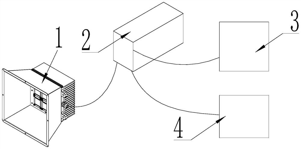
[0015] A control box 2 is set on one side of the strobe light 1, an external power supply 3 is set on one side of the control box 2, an external encoder 4 is set on one side of the external power supply 3, a wire is set between the strobe light 1 and the control box 2, and the control box 2 is connected to the external Wires are respectively arranged between the power supply 3 and the external encoder 4 .

Embodiment 2

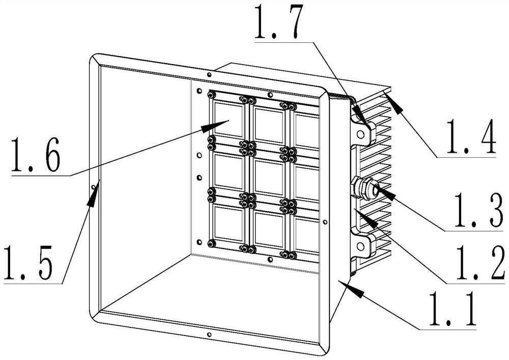
[0017] The structure of the strobe light 1 is as follows: the rear end of the lampshade 1.1 is provided with a lamp panel fixing plate 1.2, the rear end of the lamp panel fixing plate 1.2 is provided with a radiator 1.4, and one side of the lamp panel fixing plate 2 is provided with a cable waterproof connector 1.3, and the lamp panel is fixed. Light boards 1.6 are evenly distributed on the front side of the board 1.2, and the lamp boards 1.6 are located in the lampshade 1.1, and the front end of the lampshade 1.1 is provided with a phenanthrene mirror 1.5.

Embodiment 3

[0019] The strobe light 1 is installed on the detection site, the external power supply 3 and the line are used to supply power to the control box 2, the external encoder 4 is connected to the line to input signals to the control box 2, and the strobe power control circuit in the control box 2 is turned on and off To achieve the strobe effect of the strobe light 1, to meet the light supplement requirements of various high-speed cameras, the high-speed camera collects the image information that meets the requirements under the condition of supplementary light of the lamp, and calculates the detection results through computer processing.


PUM


Abstract

The invention discloses a using method of a high-power high-frequency stroboscope lamp for rail visual inspection. According the using method , a control box is arranged on one side of a stroboscope lamp, an external power source is arranged on one side of the control box, an external encoder is arranged on one side of the external power source, a lead wire is arranged between the stroboscope lamp and the control box, and lead wires are arranged between the control box and the external power source and between the control box and the external encoder respectively. The using method solves the problem that light supplement of a common light source in the rail visual inspection industry cannot adapt to various high-speed cameras, the light supplement requirements that the light source is short in exposure time, high in flash frequency and high in brightness and can be automatically controlled are met, and a better light supplement function is provided for application of more high-speed cameras in rail visual inspection.

Description

technical field [0001] The invention relates to the field of rail visual detection equipment, in particular to a method for using a high-power high-frequency strobe light for rail visual detection. Background technique [0002] At present, in the railway visual inspection industry, train wheels, railway tracks, train pantographs and various railway train equipment, etc., need a high-power lamp with short exposure time and high-frequency flashing to realize the visual inspection of them. At present, most of them are Ordinary light sources are artificially irradiated for detection, the light source brightness is low, the exposure time is long, the power is low, and the effect and efficiency are low. [0003] In view of the above reasons, a method for using a high-power high-frequency strobe light for rail visual inspection is now developed. Contents of the invention [0004] The purpose of the present invention is to overcome the deficiencies in the prior art, provide a met...

Claims


Application Information

Patent Timeline
Patent Type & Authority Applications(China)
IPC IPC(8): G01N21/01
CPCG01N21/01G01N2021/0112
Inventor 崔志远魏玉杰蔡玉龙
Owner 志强视觉(洛阳)科技发展有限公司
Learn More