Charged Particle Beam Apparatus

Active Publication Date: 2014-10-02
ASML NETHERLANDS BV
View PDF40 Cites 4 Cited by
  • Summary
  • Abstract
  • Description
  • Claims
  • Application Information

AI Technical Summary

Benefits of technology

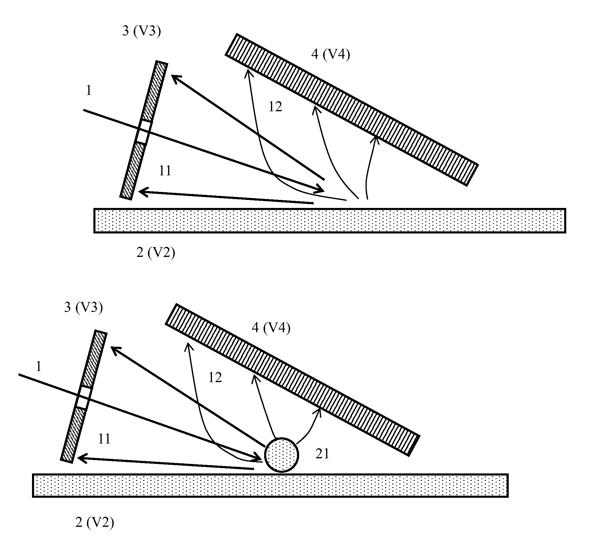
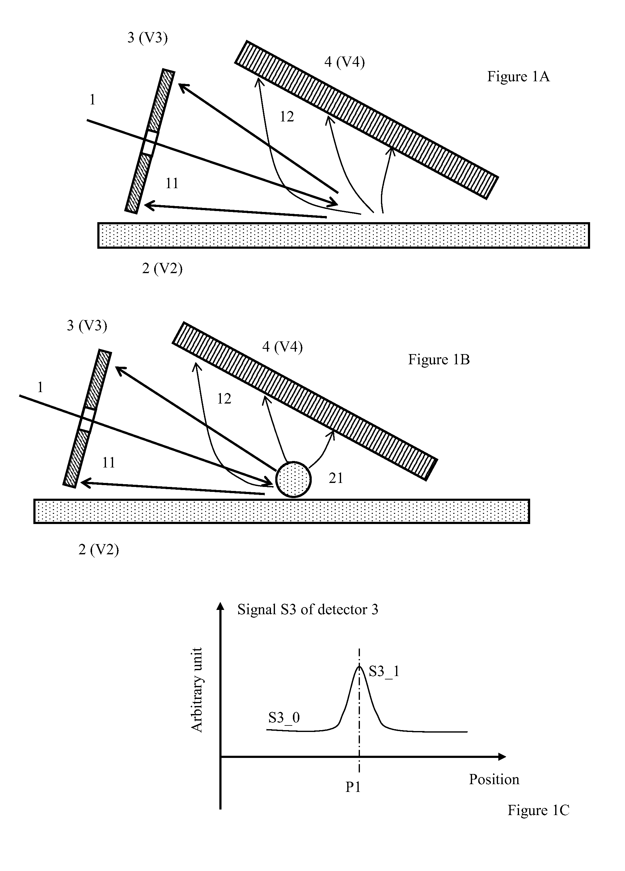
This patent describes an electron beam apparatus that uses LVSEM technology to inspect particles on a sample surface. The apparatus has a high sensitivity and throughput for detecting particles. The objective lens and condenser lens are compacted using permanent magnets, which allows for better illumination of the electron beam and reduces the size of the apparatus. The invention also configures the apparatus to accommodate multiple compact columns for inspecting multiple areas of a sample simultaneously. This technology is particularly useful for inspecting particles in semiconductor yield management.

Problems solved by technology

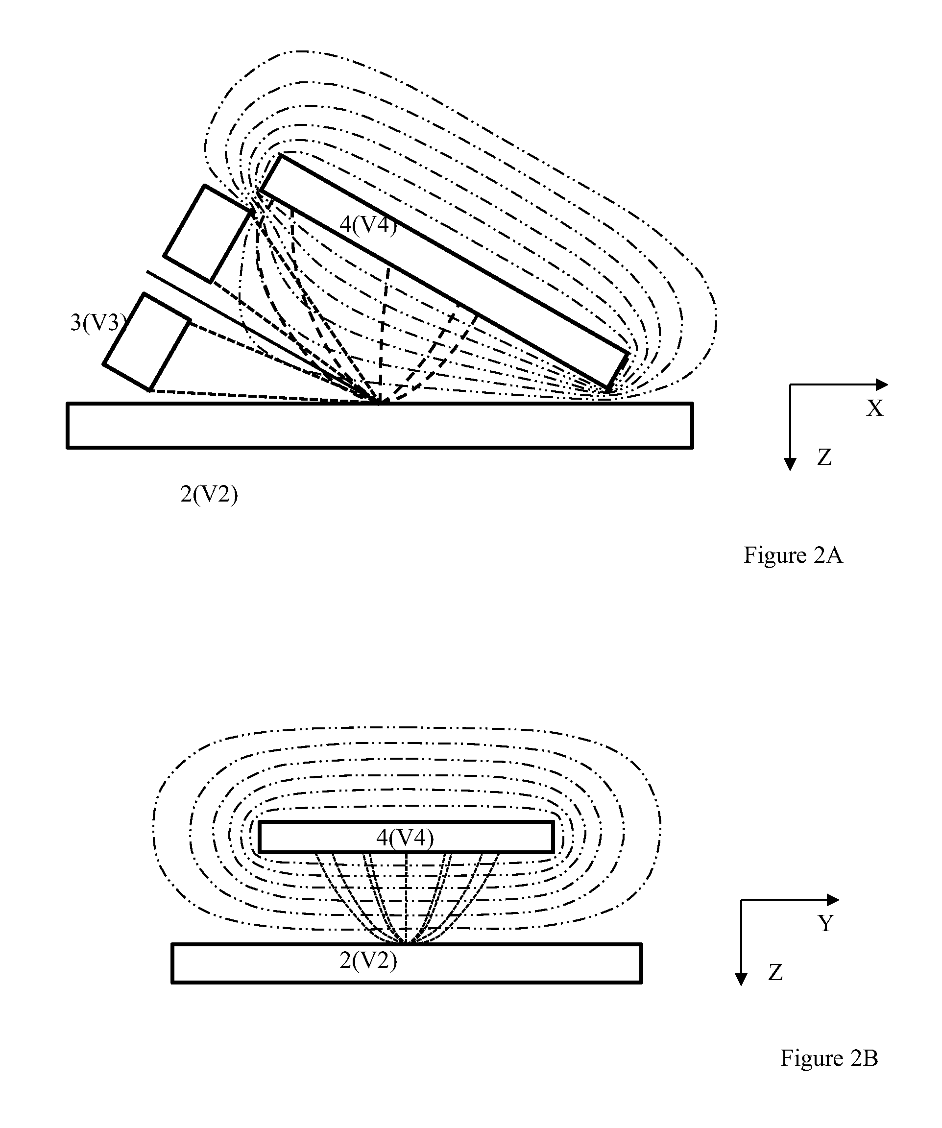
Secondly, in the column, the objective lens and / or the condenser lens are compacted by using permanent magnets.

Method used


Image

  • Charged Particle Beam Apparatus
  • Charged Particle Beam Apparatus
  • Charged Particle Beam Apparatus

Examples


Embodiment Construction

[0037]Various example embodiments of the present invention will now be described more fully with reference to the accompanying drawings in which some example embodiments of the invention are shown. Without limiting the scope of the protection of the present invention, all the description and drawings of the embodiments will exemplarily be referred to an electron beam. However, the embodiments are not be used to limit the present invention to specific charged particles.

[0038]In the drawings, relative dimensions of each component and among every component may be exaggerated for clarity. Within the following description of the drawings the same or like reference numbers refer to the same or like components or entities, and only the differences with respect to the individual embodiments are described.

[0039]Accordingly, while example embodiments of the invention are capable of various modifications and alternative forms, embodiments thereof are shown by way of example in the drawings and...


PUM


Abstract

The present invention provides apparatuses to inspect small particles on the surface of a sample such as wafer and mask. The apparatuses provide both high detection efficiency and high throughput by forming Dark-field BSE images. The apparatuses can additionally inspect physical and electrical defects on the sample surface by form SE images and Bright-field BSE images simultaneously. The apparatuses can be designed to do single-beam or even multiple single-beam inspection for achieving a high throughput.

Description

CLAIM OF PRIORITY[0001]This application claims the benefit of priority of U.S. provisional application No. 61 / 804,794 entitled to inventors filed Mar. 25, 2013 and entitled “Charged Particle Beam Apparatus”, the entire disclosures of which are incorporated herein by reference.BACKGROUND OF THE INVENTION[0002]1. Field of the Invention[0003]The present invention relates to a charged particle beam apparatus which employs a scanning electron microscope (SEM) to inspect particles and / or defects on a sample surface. More particularly, it relates to a low-voltage scanning electron microscope (LVSEM) for inspecting particles and / or defects on surfaces of wafers or masks in semiconductor manufacturing industry.[0004]2. Description of the Prior Art[0005]In semiconductor manufacturing industry, sometime particles appear and remain on surfaces of masks and / or wafers during semiconductor fabrication process for some reasons, which impact the yield to a great degree. To monitor and therefore ensu...

Claims


Application Information

Patent Timeline
IPC IPC(8): H01J37/26
CPCH01J37/261H01J37/244H01J37/28H01J2237/24495H01J2237/24528H01J2237/2804H01J2237/2806H01J2237/2814H01J37/026H01J37/10H01J37/14H01J37/20H01J37/22H01J37/285H01J37/292H01J2237/04926H01J2237/1405H01J2237/24475H01J2237/2801
Inventor CHEN, ZHONGWEIJAU, JACKREN, WEIMING
Owner ASML NETHERLANDS BV
Why Eureka
Try Eureka