
Electric isolators for couplings

Inactive Publication Date: 2011-12-22
GENERAL ELECTRIC CO
View PDF15 Cites 18 Cited by
  • Summary
  • Abstract
  • Description
  • Claims
  • Application Information

AI Technical Summary

Benefits of technology

[0014]FIG. 6 is a cut-away side view of a connection assembly that provides radial barriers to debris according to one embodiment; and

Problems solved by technology

If current is transmitted to the rotor of the turbine, there is a possibility of electrical arcing from the rotor to the bearing surfaces, which can cause damage and potentially failure of the bearings.

Method used


Image

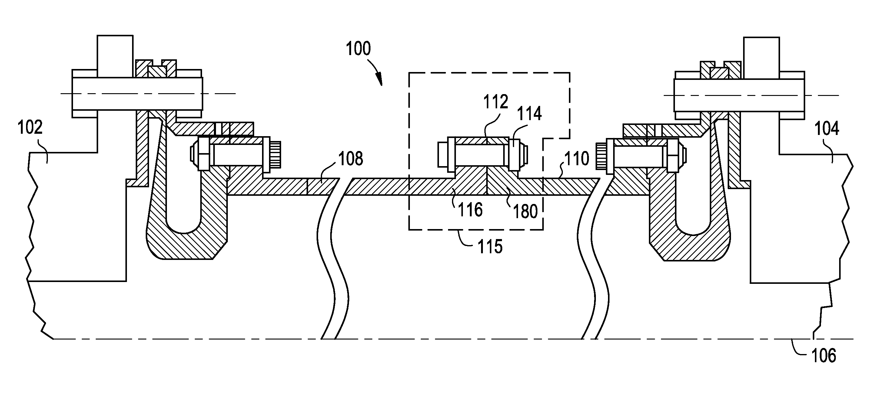
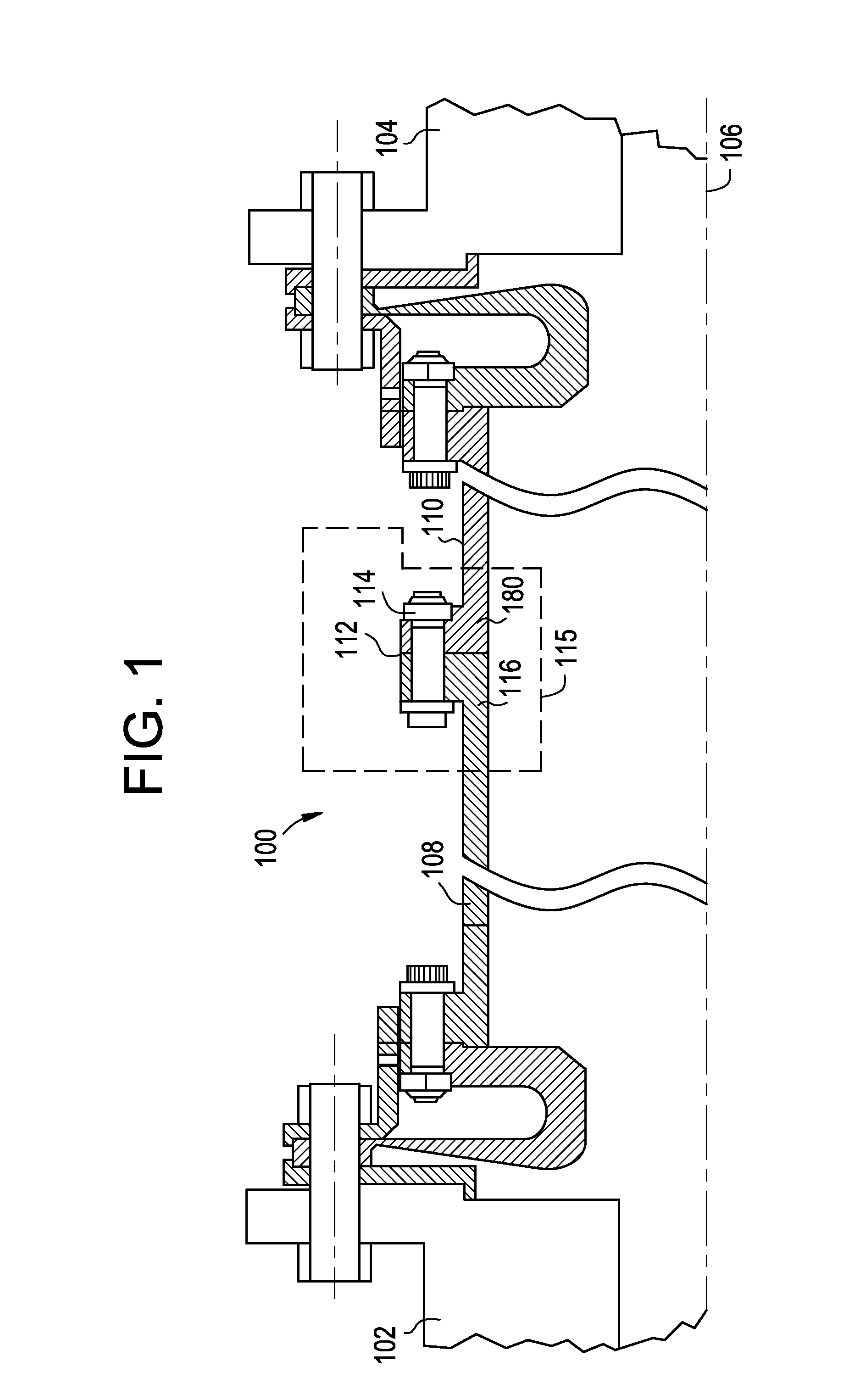
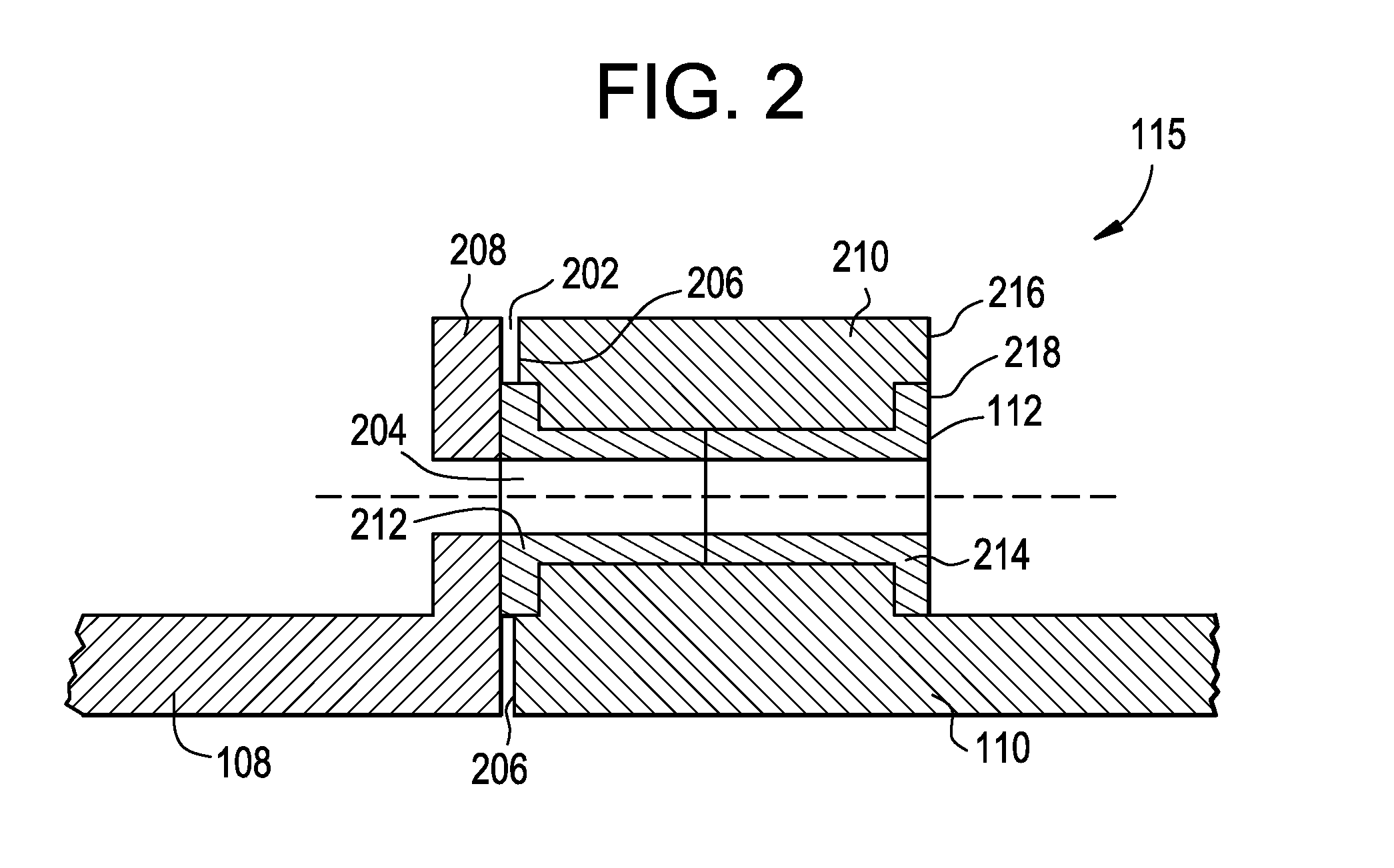
  • Electric isolators for couplings
  • Electric isolators for couplings
  • Electric isolators for couplings

Examples


Embodiment Construction

[0017]As described above, the prevailing approach to providing electrical isolation included fiberglass reinforced epoxy (FG / Ep) components. Although FG / Ep provides good isolation, experience and analysis have shown that FG / Ep may exhibit failure due to high stress (crushing of fiberglass). In addition, FG / Ep components may experience radial growth and deformation due to non-uniform properties (properties are dependent on direction of fiberglass reinforcement); may wear and degrade over time and have a low coefficient of friction (static =0.1) when in contact with steel which may result in low torque transmission through friction which can cause loading of connecting members in shear.

[0018]Accordingly, embodiments of the present invention may provide a more wear resistant and still electrically isolating material at the junction of a driving portion and a driven portion of a coupling. In particular, the material may be in the form of bushings formed of ceramic.

[0019]In addition, emb...


PUM


Abstract

A transfer device includes a first portion having a first portion flange and a second portion having a second portion flange. The device also includes one or more isolating members disposed at least partially within the second portion flange and at least partially between the first portion flange and the second portion flange, the one or more isolating members electrically isolating the first portion from the second portion. The device also includes a fastener passing through one of the one or more isolating members, the first portion flange and the second portion flange and holding the first portion flange and the second portion flange in a fixed relationship to one another.

Description

BACKGROUND OF THE INVENTION[0001]The subject matter disclosed herein relates to couplings and, in particular, to electrical isolators used for couplings.[0002]Many applications require that rotating shafts be coupled together. For example, generators are driven by industrial turbines to produce electricity. A load coupling is often used to connect the shafts of the generator and the turbine. The coupling is typically electrically insulated to prevent current traveling down the rotor shafts. If current is transmitted to the rotor of the turbine, there is a possibility of electrical arcing from the rotor to the bearing surfaces, which can cause damage and potentially failure of the bearings.[0003]In more detail, in one class of couplings for rotating shafts, a drive portion of the coupling is coupled to a driving shaft by a group of circumferentially spaced fasteners. A driven portion of such a coupling is similarly coupled to a driven shaft. The two parts of the coupling are then cou...

Claims


Application Information

Patent Timeline
IPC IPC(8): F16D1/033F16D1/02
CPCF01D5/026F05D2300/211F05D2300/2112F05D2300/22Y10T403/645F16D1/033F16D1/076F16D3/72Y10T403/64F05D2300/222F16B2200/50F16B2200/506
Inventor CAIRO, RONALD RALPHGRAHAM, NICHOLAS SIMON
Owner GENERAL ELECTRIC CO
Learn More