
Massively scalable multilayered load balancing based on integrated control and data plane

Inactive Publication Date: 2011-12-22
VERIZON PATENT & LICENSING INC
View PDF6 Cites 46 Cited by
  • Summary
  • Abstract
  • Description
  • Claims
  • Application Information

AI Technical Summary

Benefits of technology

[0010]The teachings disclosed herein relate to methods and systems for massively scalab

Problems solved by technology

A server that is overloaded or has some kind of health problem will not be able to ensure a reasonable response time.
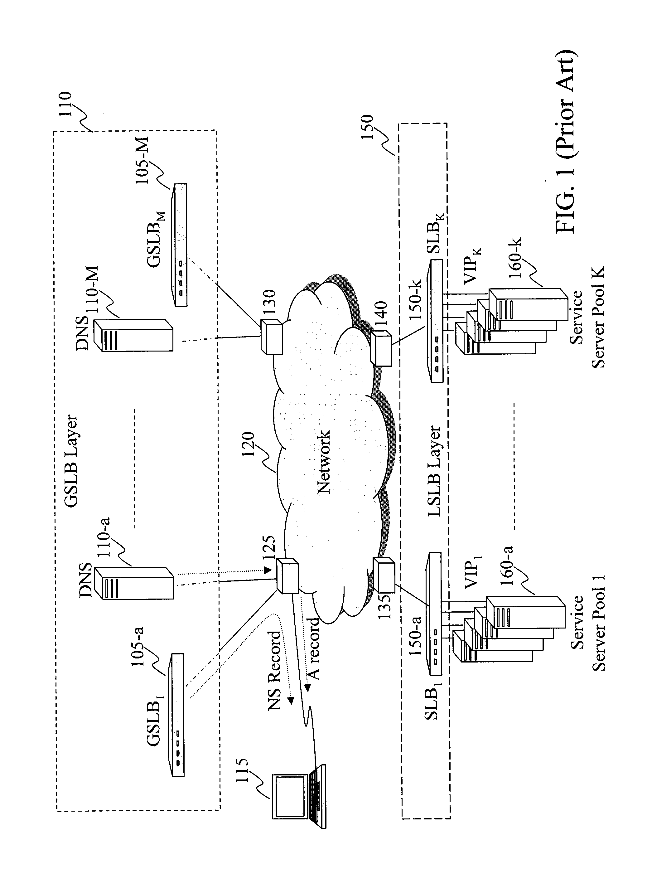
There are various problems associated with this conventional load balancing scheme.
First, there are potentially multiple points of failure.
For instance, a GSLB may fail to provide an NS record.
When the client uses the NS record to find a DNS server, this may also fail.
In addition, once the client receives the VIP address, it may fail on subsequent attempts to get connected to a particular server to receive the requested service.
If the client fails to connect to a server corresponding to a given VIP address (e.g., due to the fact that the server is down), the client will have no way to know that there may be alternative VIP addresses corresponding to the same service for an indefinite period of time.
In addition to introducing multiple points of failure, the fact that the conventional load balancing scheme requires multiple layers of load balancers also leads to other disadvantages.
When all these layers of load balancers operate in a serial manner, it substantially increases packet latencies.
In addition, multiple layers of load balancers increase the number of devices, the deployment costs, the consumption of space, power, and costs for cooling.

Method used


Image

  • Massively scalable multilayered load balancing based on integrated control and data plane
  • Massively scalable multilayered load balancing based on integrated control and data plane
  • Massively scalable multilayered load balancing based on integrated control and data plane

Examples


Embodiment Construction

[0032]In the following detailed description, numerous specific details are set forth by way of examples in order to provide a thorough understanding of the relevant teachings. However, it should be apparent to those skilled in the art that the present teachings may be practiced without such details. In other instances, well known methods, procedures, components, and / or circuitry have been described at a relatively high-level, without detail, in order to avoid unnecessarily obscuring aspects of the present teachings.

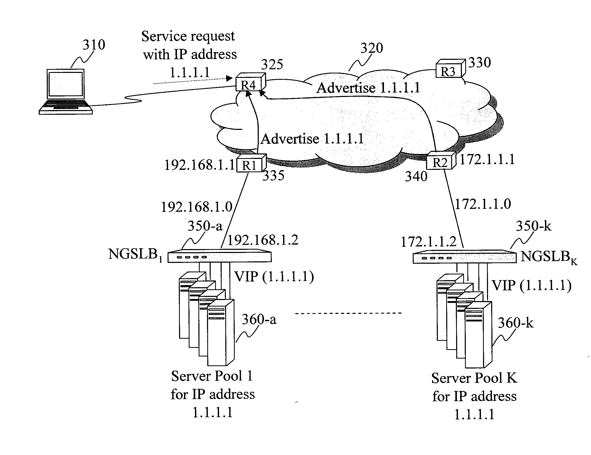
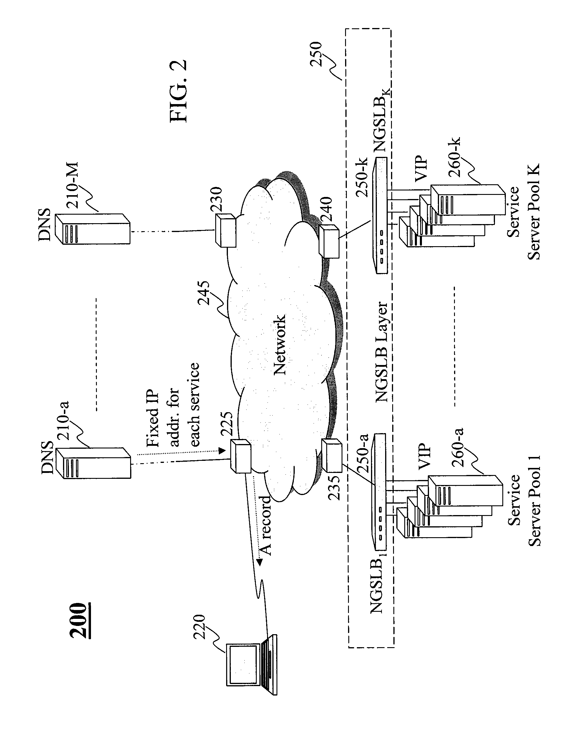
[0033]The present teaching relates to apparatus and method for multilayered load balancing with integrated control and data plane, in which the control plane is massively scalable with deterministic performance to achieve global load balancing and the data plane is designed to achieve local load balancing. FIG. 2 depicts an exemplary architecture 200 for the multilayered load balancing with integrated control and data planes. The architecture 200 comprises a client 220 th...


PUM


Abstract

Method and system for load balancing in providing a service. A request for a service, represented by a single IP address, is first received by a router in the network. The router accesses information received from one or more advertising routers in the network. Each of the advertising routers advertises, via the single IP address, the service provided by at least one server in a server pool associated with the advertising router. The advertisement includes metrics indicating a health condition of the associated server pool. The router selects a target router based on, at least in part, the metrics of the server pools associated with the advertising routers to achieve a first level load balancing and forwards the request for the service to the target router. A local server load balancer (SLB) connected with the target router then identifies a target server from the associated server pool to provide the requested service thereby to achieve a second level load balancing.

Description

BACKGROUND[0001]1. Technical Field[0002]The present teaching relates to methods, systems and programming for load balancing in telecommunications and systems incorporating the same.[0003]2. Discussion of Technical Background[0004]With the advancement of computing networks and the Internet, more and more services are provided across the network. Due to the sharp increase in the volume of business conducted on the Internet and the Internet's nature of access without boundaries in terms of geographical coverage, nearly all Internet based services are now offered by servers located in a distributed manner to allow service efficiency, load balance, or fault tolerance. For example, an Internet user may find news by visiting cnn.com from almost anywhere in the world. Although it may seem that such users are getting services from one Internet location, namely cnn.com, there may be many servers distributed around the world that all offer the same services corresponding to cnn.com. A user loc...

Claims


Application Information

Patent Timeline
IPC IPC(8): G06F15/173G06F15/167
CPCH04L29/12066H04L61/1511H04L67/1002H04L67/1027H04L67/2814H04L67/1008H04L61/4511H04L67/1001H04L67/563
Inventor KAKADIA, DEEPAKDUDA, KEN
Owner VERIZON PATENT & LICENSING INC
Learn More