
Power converter with compensation circuit for adjusting output current provided to a constant load

a compensation circuit and output current technology, applied in the direction of electric variable regulation, process and machine control, instruments, etc., can solve the problems of increasing duty cycle and/or switching frequency, reducing the amount of power delivered to the output, and misrepresenting peak input voltag

Inactive Publication Date: 2011-12-29
POWER INTEGRATIONS INC
View PDF2 Cites 39 Cited by
  • Summary
  • Abstract
  • Description
  • Claims
  • Application Information

AI Technical Summary

Problems solved by technology

This is because the controller may not realize that a portion of the ac input voltage has been blocked by a dimmer circuit, thereby reducing the amount of power delivered to the output.
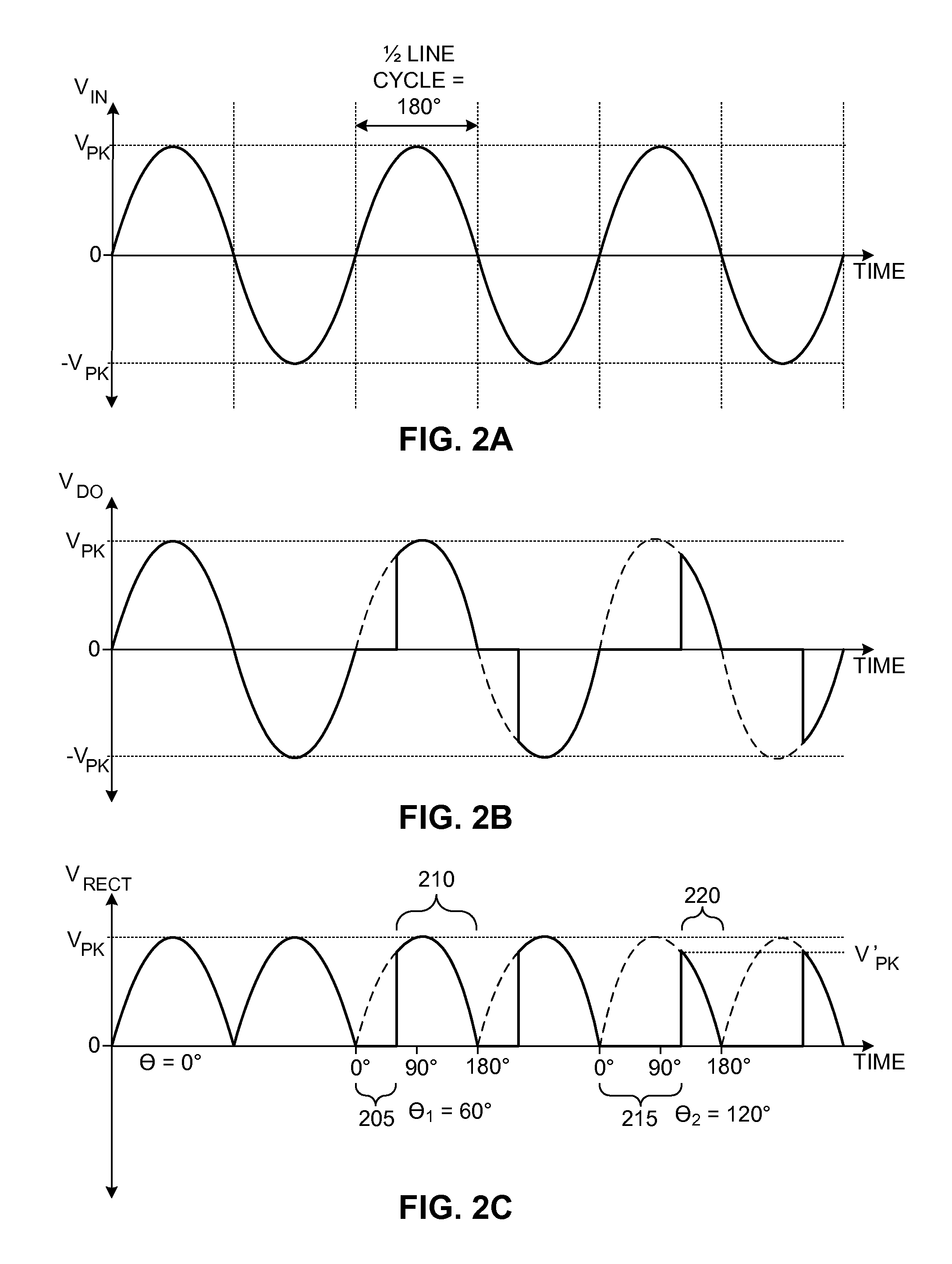
However, when a phase angle is greater than 90 degrees, the dimmer circuit may block the peak input voltage and therefore misrepresent the peak input voltage with a lower voltage.
The controller may then increase duty cycle and / or switching frequency and inadvertently increase power delivery to the output.

Method used


Image

  • Power converter with compensation circuit for adjusting output current provided to a constant load
  • Power converter with compensation circuit for adjusting output current provided to a constant load
  • Power converter with compensation circuit for adjusting output current provided to a constant load

Examples


Embodiment Construction

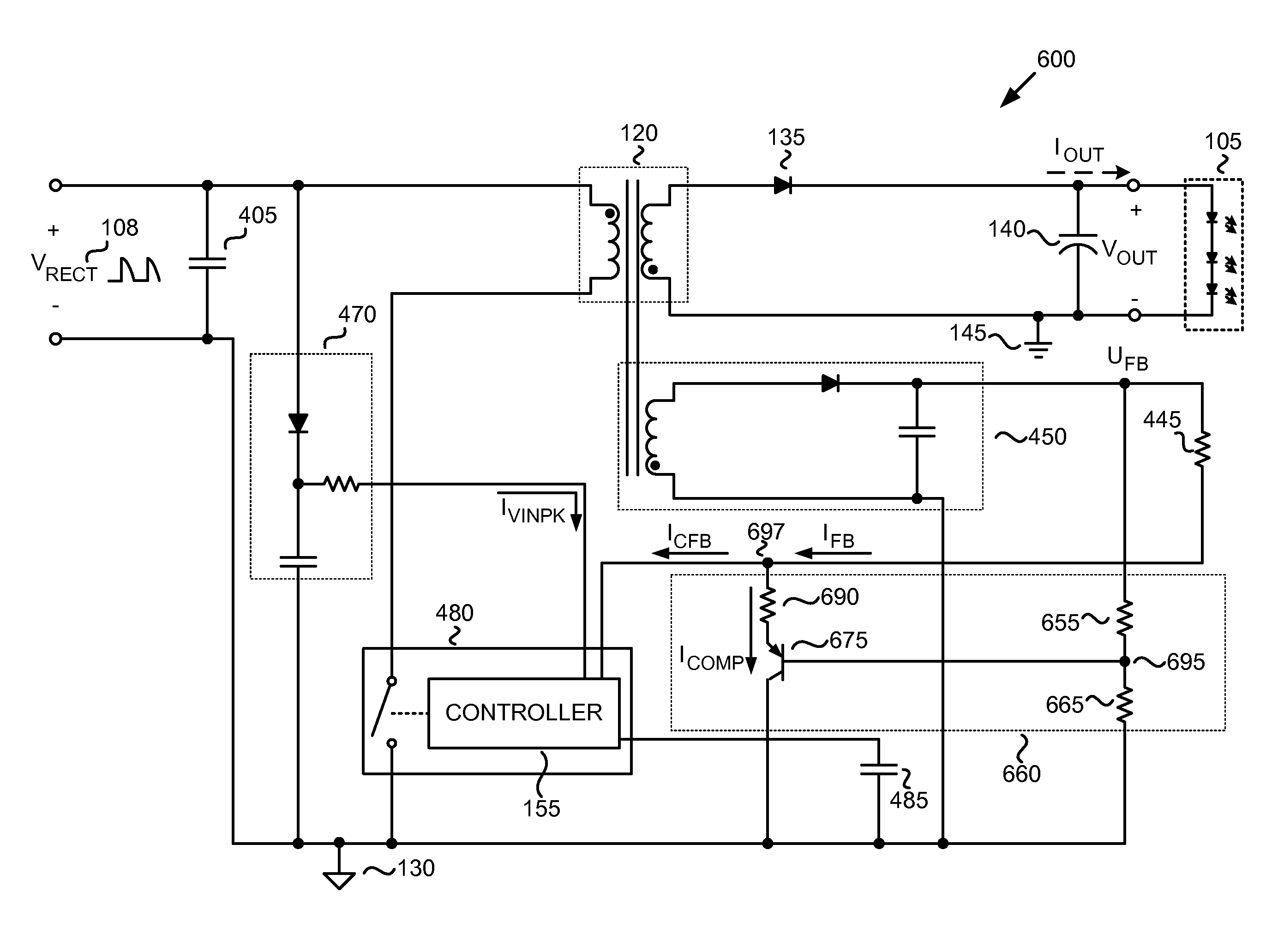
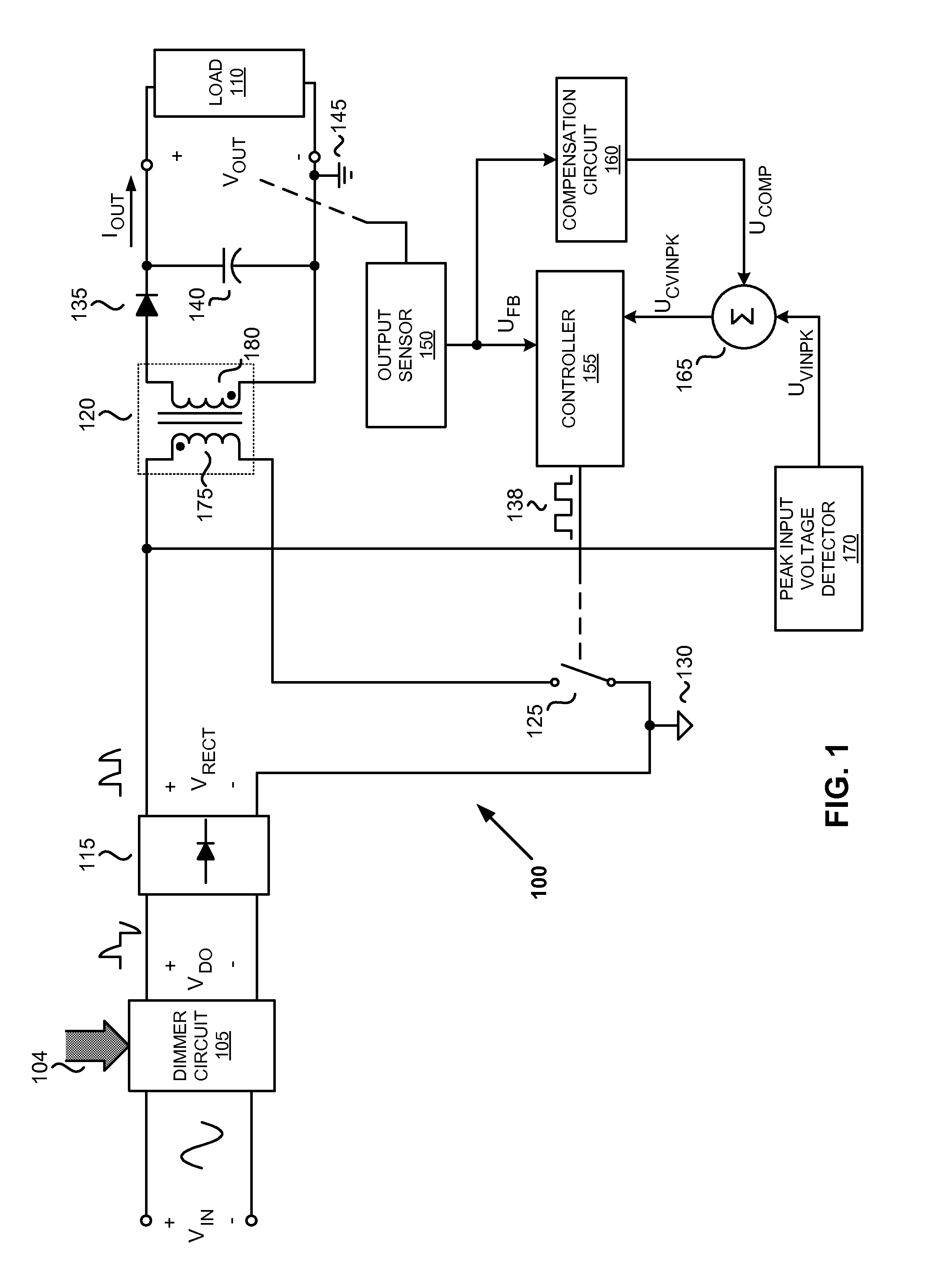
[0017]Embodiments of a power converter with a compensation circuit for adjusting output current provided to a constant load are described herein. In the following description numerous specific details are set forth to provide a thorough understanding of the embodiments. One skilled in the relevant art will recognize, however, that the techniques described herein can be practiced without one or more of the specific details, or with other methods, components, materials, etc. In other instances, well-known structures, materials, or operations are not shown or described in detail to avoid obscuring certain aspects.

[0018]Reference throughout this specification to “one embodiment”, “an embodiment”, “one example” or “an example” means that a particular feature, structure or characteristic described in connection with the embodiment or example is included in at least one embodiment of the present invention. Thus, appearances of the phrases “in one embodiment”, “in an embodiment”, “one examp...


PUM


Abstract

A power converter for constant loads includes an energy transfer element, a switch, a controller, and a compensation circuit. The energy transfer element is coupled to receive a rectified voltage having a non-blocked portion and a blocked portion, where an amount of the blocked portion corresponds to a phase angle. The controller is coupled to control switching of the switch to regulate an output current of the power converter in response to a plurality of signals. The plurality of signals includes a peak input voltage signal and a feedback signal, where the peak input voltage signal is representative of a peak input voltage of the power converter and the feedback signal is representative of the output voltage of the power converter. The compensation circuit is coupled to adjust at least one of the plurality of signals in response to the phase angle exceeding a phase angle threshold.

Description

TECHNICAL FIELD[0001]Embodiments of the present invention relate generally to power supplies, and more specifically to power supplies utilized with dimmer circuits.BACKGROUND INFORMATION[0002]Electronic devices are typically used with power conversion circuits. Switched mode power converters are commonly used due to their high efficiency, small size and low weight to power many of today's electronics. Conventional wall sockets provide a high voltage alternating current. In a switching power converter a high voltage alternating current (ac) input is converted to provide a well regulated direct current (dc) output. In operation, a switch, included in the power converter, is utilized to control the desired output current by varying the duty cycle (typically the ratio of the on time of the switch to the total switching period) and / or varying the switching frequency (the number of switching events per unit time). More specifically, a power converter controller may determine the duty fact...

Claims


Application Information

Patent Timeline
IPC IPC(8): H05B41/36H05B44/00
CPCH02M3/33507H05B33/0839H05B33/0854H05B33/0815H05B45/10H05B45/385
Inventor KANG, DOUGLASCARPENTER, JOHN A.SAVLIWALA, TAHER M.
Owner POWER INTEGRATIONS INC
Learn More