Imaging lens, optical apparatus equipped therewith, and method for manufacturing imaging lens

Active Publication Date: 2011-12-29
NIKON CORP
View PDF4 Cites 11 Cited by
  • Summary
  • Abstract
  • Description
  • Claims
  • Application Information

AI Technical Summary

Benefits of technology

[0012]According to the present invention, it is feasible to provide the downsized imaging lens having a wide angle of view, capable of preferably correcting various aberrations upon focusing on a close

Problems solved by technology

The conventional imaging lens has, however, such a problem that in the case of taking a configuration of focusing by a whole imaging lens system, a total lens length of the imaging lens extends

Method used


Image

  • Imaging lens, optical apparatus equipped therewith, and method for manufacturing imaging lens
  • Imaging lens, optical apparatus equipped therewith, and method for manufacturing imaging lens
  • Imaging lens, optical apparatus equipped therewith, and method for manufacturing imaging lens

Examples


Example

Example 1

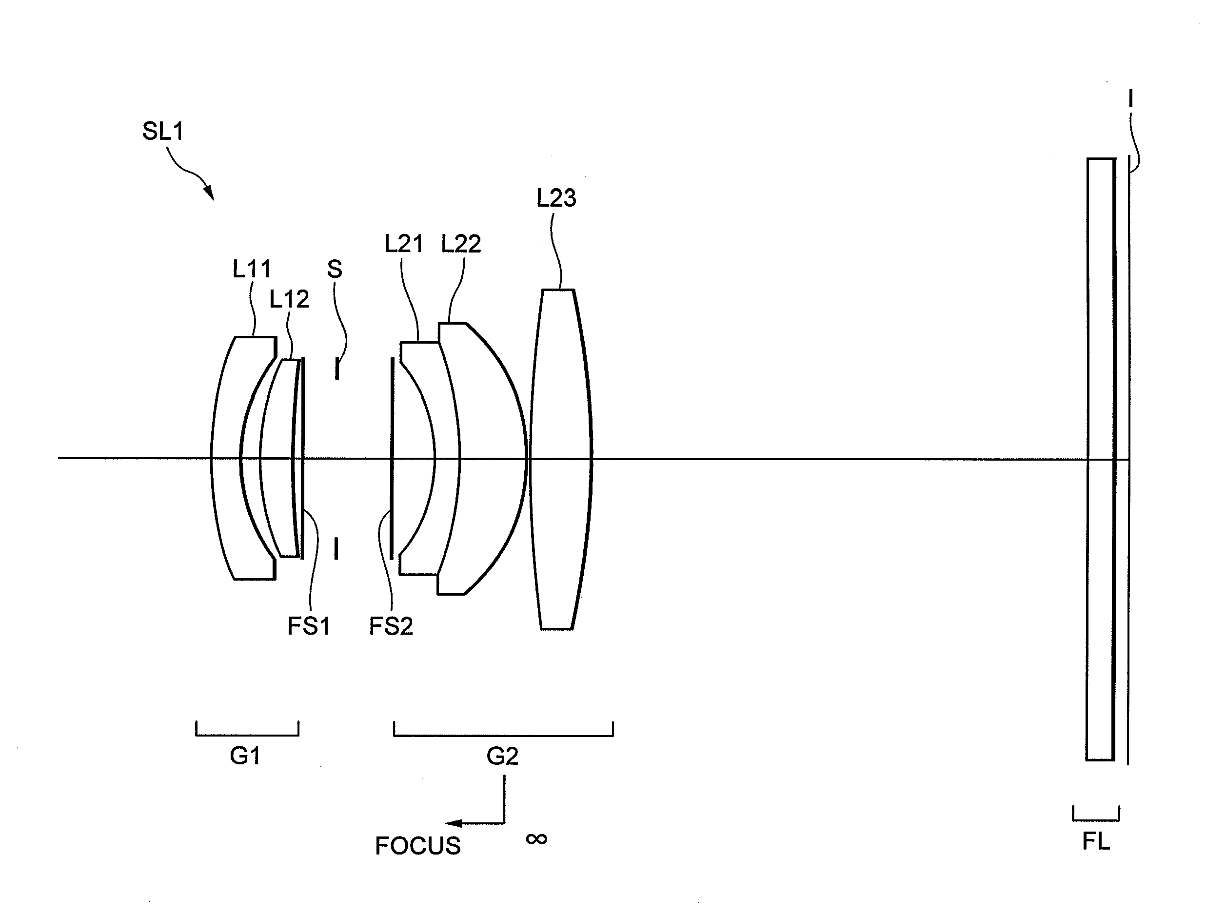
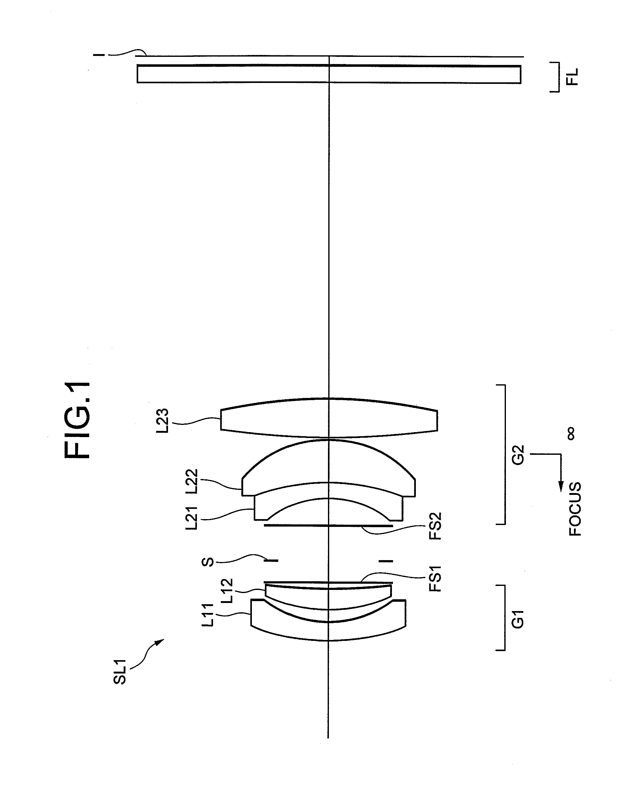
[0090]FIG. 1 is a sectional view showing a configuration of an imaging lens SL1 according to Example 1 of the present invention.

[0091]As illustrated in FIG. 1, the imaging lens SL1 according to Example 1 is composed of, in order from an unillustrated object side, a first lens group G1 having positive refractive power, a second lens group G2 spaced with an air distance from the first lens group G1 and having positive refractive power and a filter group FL spaced with an air distance from the second lens group G2.

[0092]The first lens group G1 is composed of, in order from the object side, a negative meniscus lens L11 (a first lens component) with its convex surface directed to the object side and a positive meniscus lens L12 (a second lens component) with its convex surface directed to the object side. The second lens group G2 is composed of a cemented lens (a third lens component) constructed by a negative lens L21 with its concave surface directed to the object side cemente...

Example

Example 2

[0107]FIG. 3 is a view showing a lens configuration of an imaging lens SL2 according to Example 2 of the present invention.

[0108]As illustrated in FIG. 3, the imaging lens SL2 according to Example 2 is composed of, in order from an unillustrated object side, a first lens group G1 having positive refractive power, a second lens group G2 spaced with an air distance from the first lens group G1 and having positive refractive power and a filter group FL spaced with an air distance from the second lens group G2.

[0109]The first lens group G1 is composed of, in order from the object side, a negative meniscus lens L11 (the first lens component) with its convex surface directed to the object side and a positive meniscus lens L12 (the second lens component) with its convex surface directed to the object side. The second lens group G2 is composed of a cemented lens (the third lens component) constructed by a negative lens L21 with its concave surface directed to the object side cement...

Example

Example 3

[0114]FIG. 5 is a sectional view showing a lens configuration of an imaging lens SL3 according to Example 3 of the present invention.

[0115]As illustrated in FIG. 5, the imaging lens SL3 according to Example 3 is composed of, in order from an unillustrated object side, a first lens group G1 having positive refractive power, a second lens group G2 spaced with an air distance from the first lens group G1 and having positive refractive power and a filter group FL spaced with an air distance from the second lens group G2.

[0116]The first lens group G1 is composed of, in order from the object side, a negative meniscus lens L11 (the first lens component) with its convex surface directed to the object side and a positive meniscus lens L12 (the second lens component) with its convex surface directed to the object side. The second lens group G2 is composed of a cemented lens (the third lens component) constructed by a negative lens L21 with its concave surface directed to the object s...


PUM


Abstract

The imaging lens includes, in order from an object side, a first lens group having positive refractive power; and a second lens group having the positive refractive power, the first lens group being fixed with respect to an image plane, the second lens group being moved toward the object side to adjust a focus on a close object, and a given conditional expression being satisfied, thereby disclosing a downsized imaging lens having a wide angle of view, capable of preferably correcting various aberrations upon focusing on a close object from an infinitely distant object and having high optical performance over an entire picture, an optical apparatus including the imaging lens and an imaging lens manufacturing method.

Description

[0001]The disclosure of the following priority application is herein incorporated by reference:[0002]Japanese Patent Application No. 2010-142921 filed on Jun. 23, 2010.BACKGROUND OF THE INVENTION[0003]1. Field of the Invention[0004]The present invention relates to an imaging lens, an optical apparatus equipped with the imaging lens, and a method for manufacturing the imaging lens.[0005]2. Related Background Art[0006]In a camera for photography, a video camera, etc., a downsized lens, of which an angle of view is on the order of 50 degrees and an f-number is relatively small (bright), has hitherto been exemplified by an imaging lens including, in order from an object side, a first lens group composed of a negative lens and a positive lens, an aperture stop and a second lens group composed of a cemented lens constructed by a negative lens cemented with a positive lens, and a positive lens (refer to, e.g., Japanese Patent Application Laid-Open Publication No. 2001-56434).[0007]The conv...

Claims


Application Information

Patent Timeline
IPC IPC(8): G02B15/14
CPCG02B13/004G02B27/646G02B13/006G02B13/0045
Inventor TAKE, TOSHINORI
Owner NIKON CORP
Why Eureka
Try Eureka