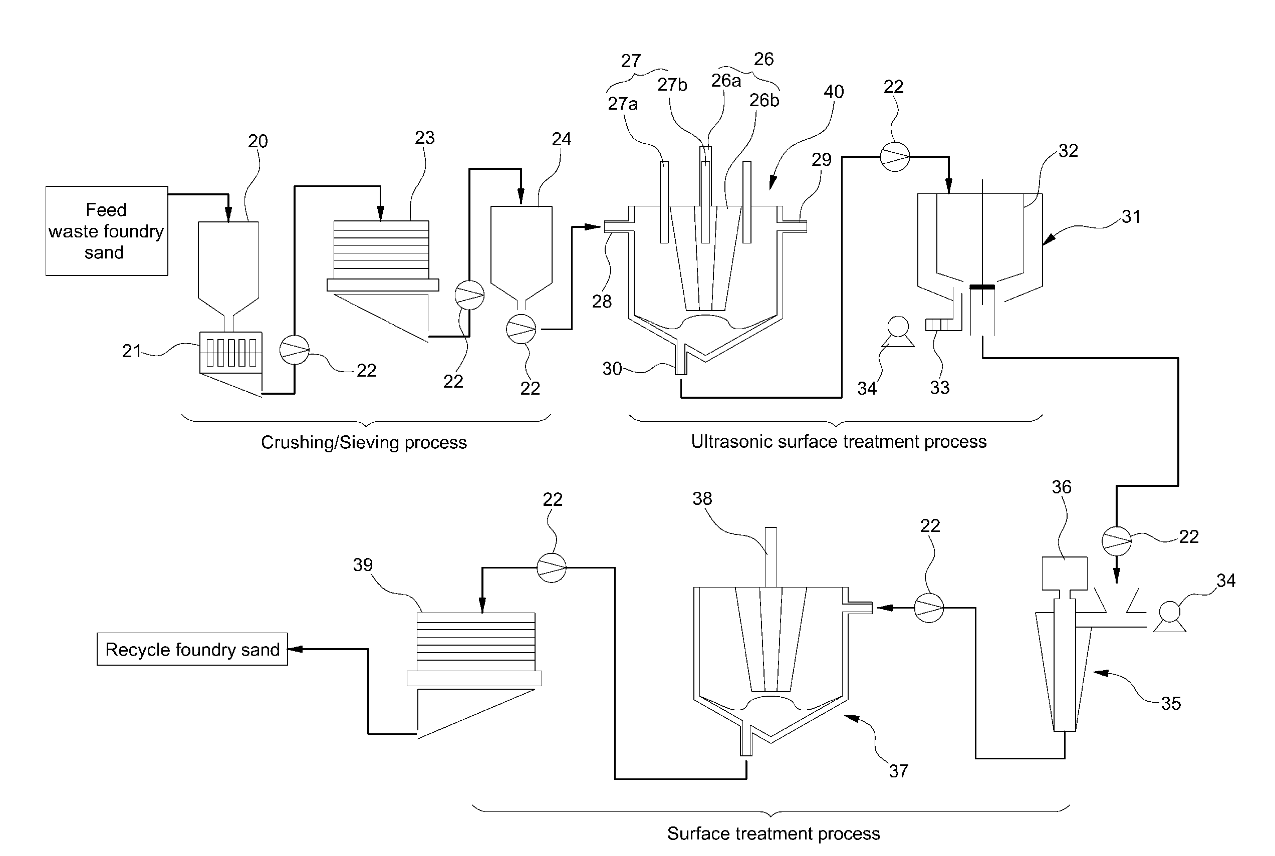
Separation system for waste foundry sand binder using ultrasonic waves
a technology separation system, which is applied in the direction of gas current separation, mold making apparatus, cleaning using liquids, etc., can solve the problems of conventional expensive heat treatment and surface treatment processes, and achieve the effect of reducing the number of surface treatment processes and reducing the recycling cost of waste foundry sand
- Summary
- Abstract
- Description
- Claims
- Application Information
AI Technical Summary
Benefits of technology
Problems solved by technology
Method used
Image

Examples
Embodiment Construction
[0039]Hereinafter reference will now be made in detail to various embodiments of the present invention, examples of which are illustrated in the accompanying drawings and described below. While the invention will be described in conjunction with exemplary embodiments, it will be understood that present description is not intended to limit the invention to those exemplary embodiments. On the contrary, the invention is intended to cover not only the exemplary embodiments, but also various alternatives, modifications, equivalents and other embodiments, which may be included within the spirit and scope of the invention as defined by the appended claims.
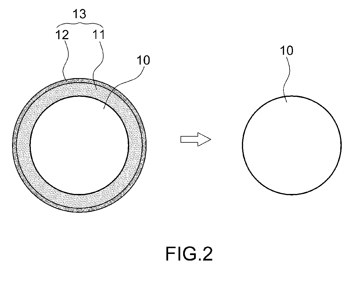
[0040]The present invention provides a system for separating a binder from waste foundry sand, for example as depicted in the schematic diagram of FIG. 2 which shows removal of binder 13 from waste foundry sand 10. In preferred embodiments, the binder is separated from the waste foundry sand using ultrasonic waves. The present methods can...
PUM
 Abstract
Description
Claims
Application Information
 - Generate Ideas
- Intellectual Property
- Life Sciences
- Materials
- Tech Scout
- Unparalleled Data Quality
- Higher Quality Content
- 60% Fewer Hallucinations
Browse by: Latest US Patents, China's latest patents, Technical Efficacy Thesaurus, Application Domain, Technology Topic, Popular Technical Reports.
© 2025 PatSnap. All rights reserved.Legal|Privacy policy|Modern Slavery Act Transparency Statement|Sitemap|About US| Contact US: help@patsnap.com