
Nozzle plate and method for manufacturing the nozzle plate, and inkjet printer head with the nozzle plate

Inactive Publication Date: 2012-01-05
SAMSUNG ELECTRO MECHANICS CO LTD
View PDF6 Cites 14 Cited by
  • Summary
  • Abstract
  • Description
  • Claims
  • Application Information

AI Technical Summary

Benefits of technology

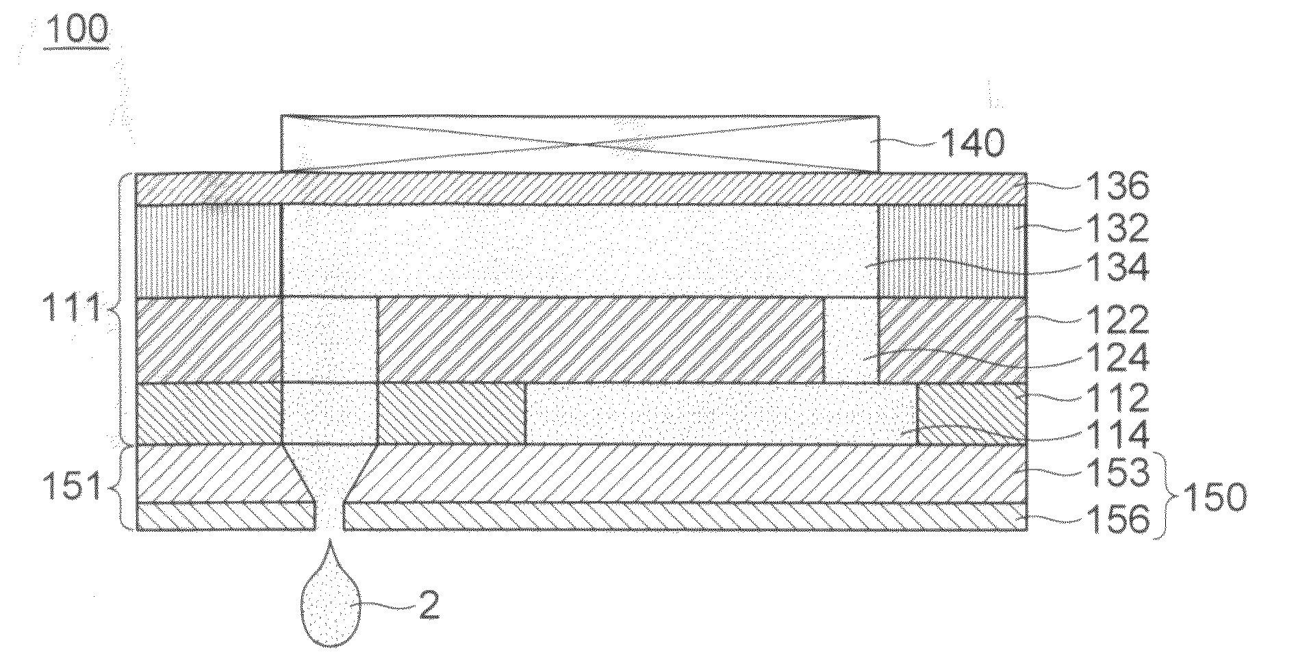
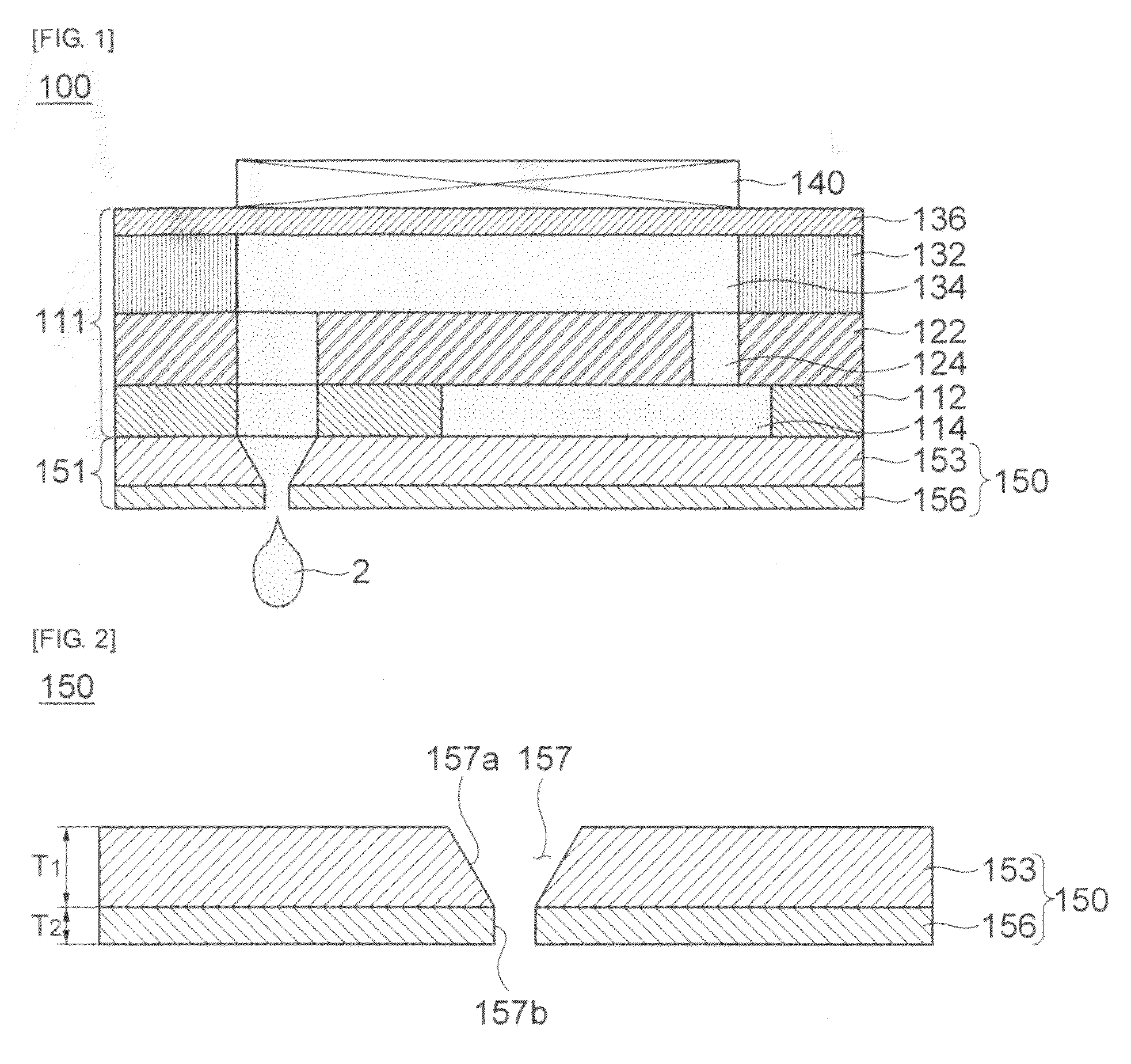
[0009]The present invention has been proposed in order to overcome the above-described problems and it is, therefore, an object of the present invention to provide a nozzle plate for improving a discharge precision of ink, and an inkjet printer head with the nozzle plate.
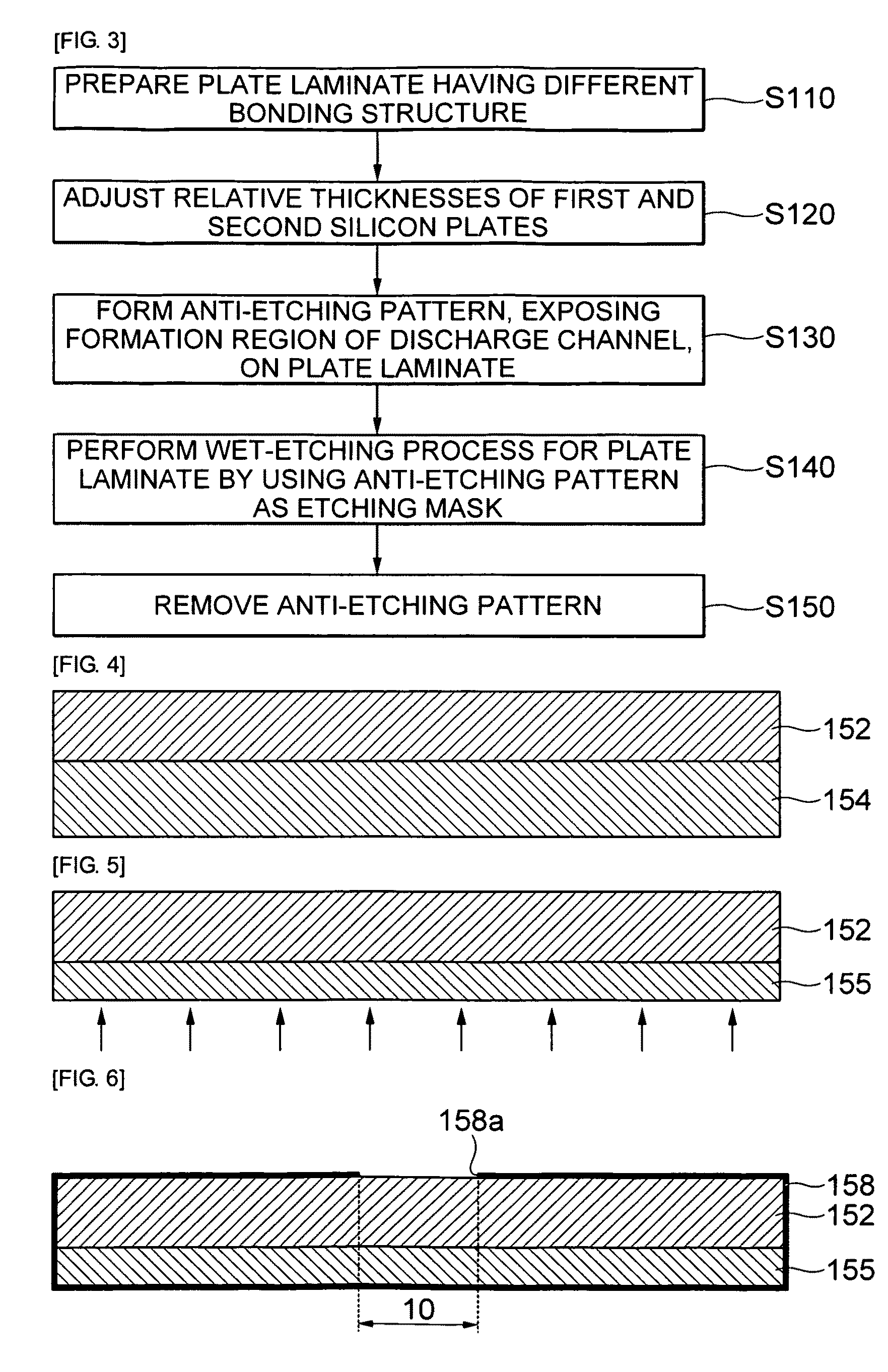
[0010]Further, another object of the present invention is to provide a method for manufacturing a nozzle plate for improving a discharge precision of ink.

Problems solved by technology

However, in case where the nozzle plate is formed using the wet-etching process, there is a limit in precisely forming the discharge channel.
If the discharge channel is used in an inkjet printer head to be completely formed, there may be a problem in that the discharge precision of ink output from the inkjet printer head is deteriorated.
However, it is actually difficult to form the discharge channel with the above-structure by performing a precise control through a wet-etching process.
Therefore, there is a problem such as a high defective rate of the manufactured nozzle plate.

Method used


Image

  • Nozzle plate and method for manufacturing the nozzle plate, and inkjet printer head with the nozzle plate
  • Nozzle plate and method for manufacturing the nozzle plate, and inkjet printer head with the nozzle plate
  • Nozzle plate and method for manufacturing the nozzle plate, and inkjet printer head with the nozzle plate

Examples


Embodiment Construction

[0052]The invention now will be described more fully hereinafter with reference to the accompanying drawings, in which exemplary embodiments of the invention are shown. This invention may, however, be embodied in many different forms and should not be construed as limited to the embodiments set forth herein. Rather, these embodiments are provided so that this disclosure will be thorough and complete, and will fully convey the scope of the invention to those skilled in the art. Like reference numerals refer to like elements throughout.

[0053]The terminology used herein is for the purpose of describing particular embodiments only and is not intended to be limiting of example embodiments. As used herein, the singular forms “a,”“an” and “the” are intended to include the plural forms as well, unless the context clearly indicates otherwise. It will be further understood that the terms “comprises” and / or “comprising,” when used in this specification, specify the presence of stated features,...


PUM

PropertyMeasurementUnit
Thicknessaaaaaaaaaa
Anisotropyaaaaaaaaaa
Crystal orientationaaaaaaaaaa

Abstract

The present invention provides a nozzle plate, the nozzle plate including: a first silicon substrate; and a second silicon substrate which has a crystal orientation different from that of the first silicon substrate and is bonded to the first silicon substrate, wherein the first silicon substrate includes a first through hole, and the second silicon substrate includes a second through hole which the first through hole communicates with, and has a different structure from that of the first through hole.

Description

CROSS-REFERENCE TO RELATED APPLICATIONS[0001]This application claims the benefit of Korean Patent Application No. 10-2010-0063316 filed with the Korea Intellectual Property Office on Jul. 1, 2010, the disclosure of which is incorporated herein by reference.BACKGROUND OF THE INVENTION[0002]1. Field of the Invention[0003]The present invention relates to a nozzle plate and a method for manufacturing the nozzle plate, and an inkjet printer head with the nozzle plate; and, more particularly, to a nozzle plate for improving a discharge precision of ink, and a method for manufacturing the nozzle plate, and an inkjet printer head with the nozzle plate.[0004]2. Description of the Related Art[0005]At present, there has been widely used a technology for implementing images through an inkjet printer. A research has recently been conducted to apply the inkjet printer technology to processes for manufacturing a color filter, a solar cell battery, an OLED, and a PCB. The inkjet printer has an inkj...

Claims


Application Information

Patent Timeline
IPC IPC(8): B41J2/14B41J2/16
CPCB41J2/14233B41J2/162B41J2/1631B41J2/1629B41J2/1623
Inventor KIM, YOUNG JAE
Owner SAMSUNG ELECTRO MECHANICS CO LTD
Learn More