Sheet-Like Connector And Manufacturing Method Thereof

a technology of connectors and sheets, applied in the direction of coupling contact members, fixed connections, coupling device connections, etc., can solve the problems of difficult to achieve uniform accumulation of accumulated material, difficulty in achieving uniform protrusion height between plurality of protrusions, and prone to warping or variations in thickness, so as to reduce the height of the connector and prevent deterioration of the spring performance. , the effect of reducing the height of the spring

Inactive Publication Date: 2012-01-05
MOLEX INC
View PDF16 Cites 4 Cited by
  • Summary
  • Abstract
  • Description
  • Claims
  • Application Information

AI Technical Summary

Benefits of technology

[0012]In one embodiment of the Present Disclosure, the spring member may be formed on the side of the sheet. According to this embodiment, the height (thickness) of the connector can be reduced.
[0013]In one embodiment of the Present Disclosure, the spring member comprises a fixating member and a movable member which extends from the fixating member towards the edge. The spring member may comprise a stand formed on the opposite side from the fixating member of the spring member with the sheet in between. According to this embodiment, when the contacting protrusion is pressed down, the entire portion of the conductive member is not undesirably lowered, and thus the deterioration of the performance of the spring can be prevented.
[0014]In one embodiment of the Present Disclosure, the spring member comprises a fixating member and a movable member which extends from the fixating member towards the edge. The fixating member may be comprised of a side fixating member which is located either on the right side or the left side of the movable member. According to this embodiment, the length of the spring member (the length of the movable member in its extended direction) is controlled, and the supporting stren...

Problems solved by technology

Some circuit boards may be prone to warping or variations in thickness.
However, when the conductive member possessing such a high protrusion is formed in the method disclosed in the '022 Application, it becomes difficult to achieve consistency in terms of the protrusion height between a plurality of protrusions, which is problematic.
However, the metal is not evenly accumulated ...

Method used


Image

  • Sheet-Like Connector And Manufacturing Method Thereof
  • Sheet-Like Connector And Manufacturing Method Thereof
  • Sheet-Like Connector And Manufacturing Method Thereof

Examples


Embodiment Construction

[0038]While the Present Disclosure may be susceptible to embodiment in different forms, there is shown in the Figures, and will be described herein in detail, specific embodiments, with the understanding that the disclosure is to be considered an exemplification of the principles of the Present Disclosure, and is not intended to limit the Present Disclosure to that as illustrated.

[0039]In the embodiments illustrated in the Figures, representations of directions such as up, down, left, right, front and rear, used for explaining the structure and movement of the various elements of the Present Disclosure, are not absolute, but relative. These representations are appropriate when the elements are in the position shown in the Figures. If the description of the position of the elements changes, however, these representations are to be changed accordingly.

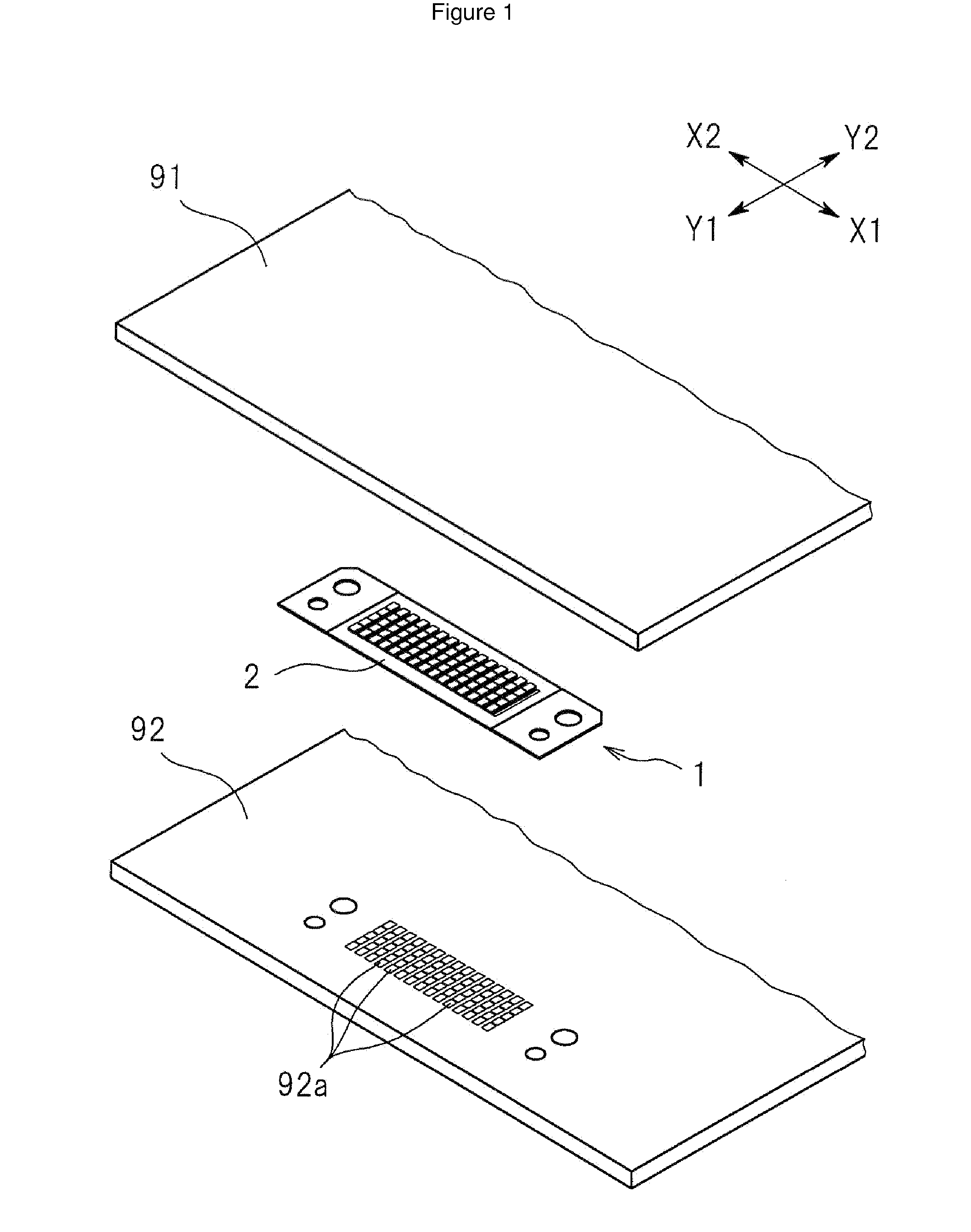
[0040]An explanation of one embodiment of the Present Disclosure is provided below with drawings utilized as a reference. FIG. 1 is an ...


PUM


Abstract

The sheet-like connector comprises a plurality of conductive members formed on one side of sheet. Each of the conductive members comprises elastically deformable spring member wherein edge thereof moves in the thickness direction of sheet, middle member which is formed on edge of spring member, and contacting protrusion which is formed on middle member and which protrudes in the thickness direction of sheet. Middle member and contacting protrusion are formed with materials which are mutually different and thus enable selective etching.

Description

REFERENCE TO RELATED APPLICATIONS[0001]The Present Disclosure claims priority to prior-filed Japanese Patent Application No. 2010-147298, entitled “Sheet-Like Connector And Manufacturing Method Thereof,” filed on 29 Jun. 2010 with the Japanese Patent Office. The content of the aforementioned patent application is fully incorporated in its entirety herein.BACKGROUND OF THE PRESENT DISCLOSURE[0002]The Present Disclosure relates, generally, to a sheet-like connector for electrically connecting two mutually-facing circuit boards, and a manufacturing method thereof.[0003]Japanese Patent Application No. 2008-233022, for example, discloses a substrate (a probe substrate) on the surface of which conductive members in contact with an electrode pad of a semiconductor wafer are provided. In the '022 Application, each conductive member formed on the probe substrate possesses a spring-like member (hereafter, the spring member) which is parallel to the probe substrate; and on an end of the spring...

Claims


Application Information

Patent Timeline
IPC IPC(8): H01R12/51H01B13/00
CPCH01R12/714H01R13/2407H01R13/03H01R12/72
Inventor NISHIKAWA, MASAKONIITSU, TOSHIHIRO
Owner MOLEX INC
Why Eureka
Try Eureka