Operation device

a technology of operation device and operation panel, which is applied in the direction of electrical apparatus casing/cabinet/drawer, instruments, computing, etc., can solve the problems of difficult to realize the appropriate feel of pressing operation, the gap between the operation panel and the case, and the entry of dust through the gap into the case, etc., to achieve good pressing feel

Active Publication Date: 2012-01-12
ALPS ALPINE CO LTD
View PDF14 Cites 54 Cited by
  • Summary
  • Abstract
  • Description
  • Claims
  • Application Information

AI Technical Summary

Benefits of technology

[0025]The present invention makes it possible to seal a gap between the case and the operation panel. Thus, outside air and dust can be effectively prevented from entering the interior of the case through the gap. Additionally, with buckling or bending of the elastic member that blocks the gap, it is possible to adjust the magnitude of an elastic rep

Problems solved by technology

Since the operation panel is movably attached to a case, a gap is often created between the operation panel and the case.
This tends to cause entry of dust through the gap into the case.
Since pressing the operation panel causes compressive deformation of the elast

Method used


Image

  • Operation device
  • Operation device
  • Operation device

Examples


Embodiment Construction

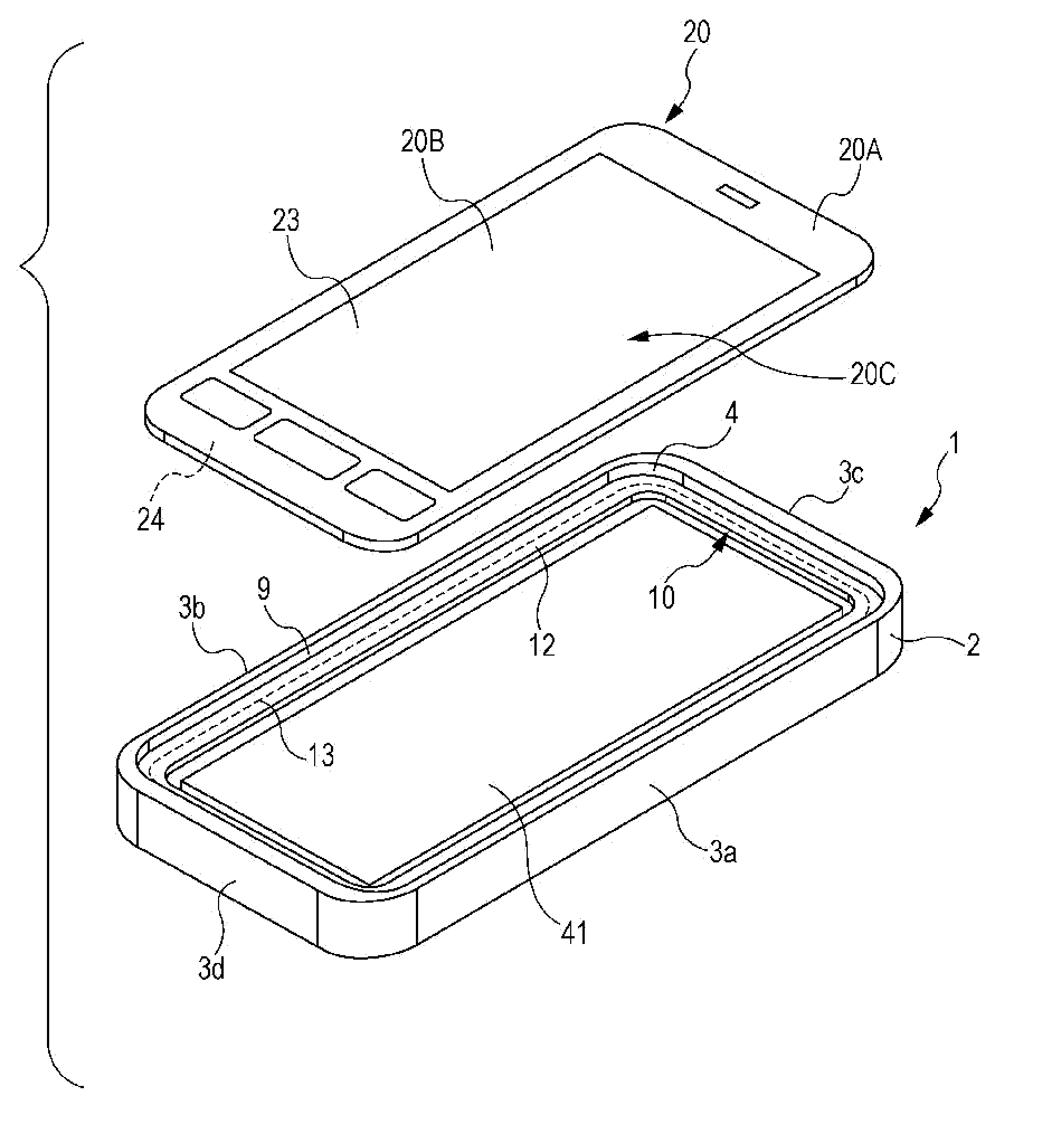
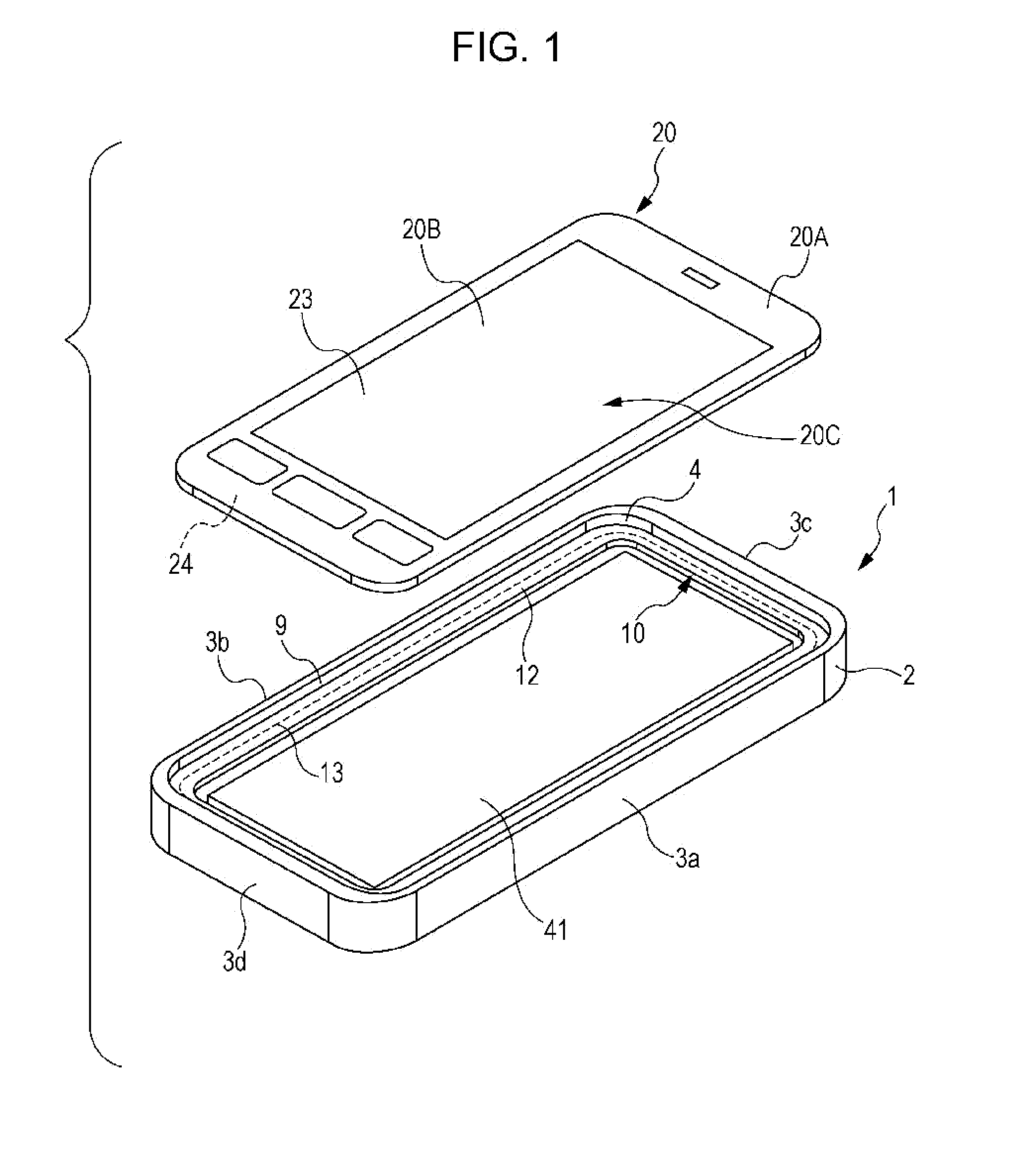
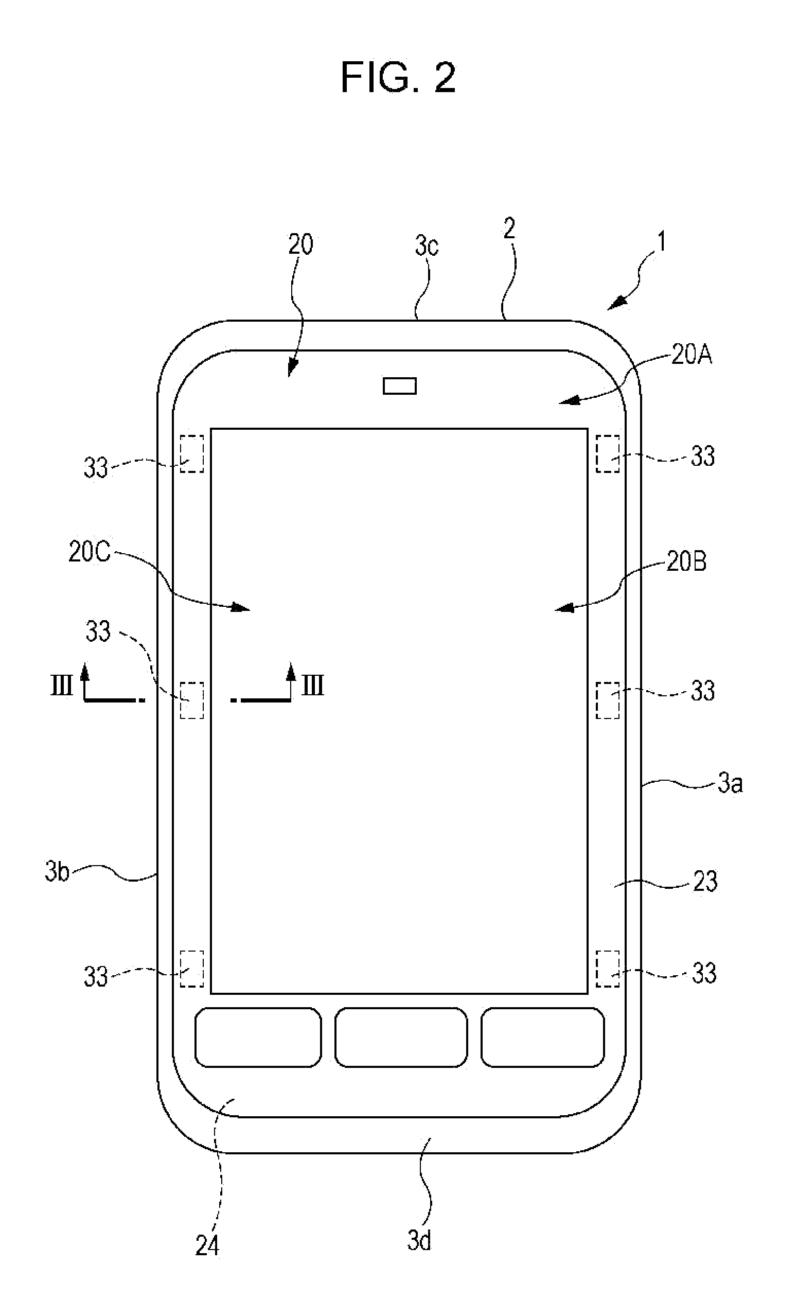
[0036]Mobile equipment 1 illustrated FIG. 1 and FIG. 2 is used, for example, as a cellular phone, a portable information processor, a portable storage apparatus, or a portable game machine.

[0037]The mobile equipment 1 includes a case 2 made of synthetic resin material. The case 2 has a right side wall 3a, a left side wall 3b, an upper side wall 3c, and a lower side wall 3d. A front part of the case 2 is an opening 4 surrounded by the side walls 3a, 3b, 3c, and 3d. The opening 4 is substantially rectangular in shape.

[0038]As illustrated in FIG. 3, a back cover 5 made of synthetic resin material is attached to the case 2 from the back side. Thus, an opening on the back side of the case 2 is covered with the back cover 5. An internal member 6 that extends toward the inside of the case 2 is formed integrally with the back cover 5. The internal member 6 is in close contact with the inner surfaces of the right side wall 3a, the left side wall 3b, the upper side wall 3c, and the lower side...


PUM


Abstract

Mobile equipment includes an operation panel disposed in an opening of a case. The operation panel includes electrode layers that constitute a position detector. The operation panel and an internal member inside the case are provided with respective electrode layers that are opposite each other and constitute a press detector. An elastic member that supports the operation panel has a fixed portion secured to the case, a support portion configured to support the operation panel, and an elastic repulsive portion. When the operation panel is pressed, the magnitude of a reaction force against the pressing force can be adjusted to an appropriate level primarily by buckling or bending of the elastic repulsive portion.

Description

CLAIM OF PRIORITY[0001]This application is a Continuation of International Application No. PCT / JP2010 / 062423 filed on Jul. 23, 2010, which claims benefit of Japanese Patent Application No. 2009-176231 filed on Jul. 29, 2009. The entire contents of each application noted above are hereby incorporated by reference.BACKGROUND OF THE INVENTION[0002]1. Field of the Invention[0003]The present invention relates to an operation device included in electronic equipment, such as mobile equipment, and operated with the touch of a finger or the like on an operation panel.[0004]2. Description of the Related Art[0005]Patent documents described below disclose operation devices equipped with an operation panel. In such an operation device, an operation panel includes a position detector, such as a capacitive position detector, capable of detecting a position where a finger or the like touches the front surface of the operation panel. Additionally, a press detector capable of detecting a press of the...

Claims


Application Information

Patent Timeline
IPC IPC(8): H05K7/00
CPCG06F3/044G06F3/0414G06F3/0445
Inventor NOMURA, HIROO
Owner ALPS ALPINE CO LTD
Why Eureka
Try Eureka