Method and apparatus for 3d metal and high-density artifact correction for cone-beam and fan-beam ct imaging

a high-density artifact and cone beam technology, applied in the field of ct imaging, can solve the problems of affecting the growth of the image, affecting so as to achieve the effect of improving the quality of the imag

Active Publication Date: 2012-01-12
UNIVERSITY OF ROCHESTER
View PDF5 Cites 21 Cited by
  • Summary
  • Abstract
  • Description
  • Claims
  • Application Information

AI Technical Summary

Benefits of technology

[0008]To solve this problem and help orthopaedists correctly monitor the growth of host-graft-host junctions, the present invention is directed to a 3D metal artifacts correction technique to correct the streaking artifacts generated by titanium implants or other similar objects. This 3D technique can be generalized for any correction of the artifacts caused by high density sub-objects, such as metal implants in orthopedic surgery and isotope seeds in cancer treatments (for example, prostate and / or breast cancer treatments).
[0009]The novelty of this technique lies in three parts. Firstly, a CBCT system is utilized to provide 3D images; hence this 3D technique can deal with high density artifacts globally. Secondly, a priori information (such as the shape information and the CT value) of high density sub-objects is acquired and used for later artifacts correction. Finally, an optimization process with iterations is applied to minimize the error and result in accurate reconstruction images of the object.

Problems solved by technology

However, the titanium plates and screws used to connect structural grafts with host bones (as seen in FIG. 1) cause streaking and shading artifacts in the reconstructed images due to their high attenuation of x-rays.
These artifacts will distort the information of bones and cause difficulties and errors when measuring their growth.
However, due to the large size of the titanium plate and screws used by orthopaedists in the reconstruction surgery, streaking artifacts are usually so severe that thresholding cannot carry out the metal segmentation without including artifacts in the segmented image.

Method used


Image

  • Method and apparatus for 3d metal and high-density artifact correction for cone-beam and fan-beam ct imaging
  • Method and apparatus for 3d metal and high-density artifact correction for cone-beam and fan-beam ct imaging
  • Method and apparatus for 3d metal and high-density artifact correction for cone-beam and fan-beam ct imaging

Examples


Embodiment Construction

[0019]A preferred embodiment of the present invention will be set forth in detail with reference to the drawings, in which like reference numerals refer to like elements or steps throughout.

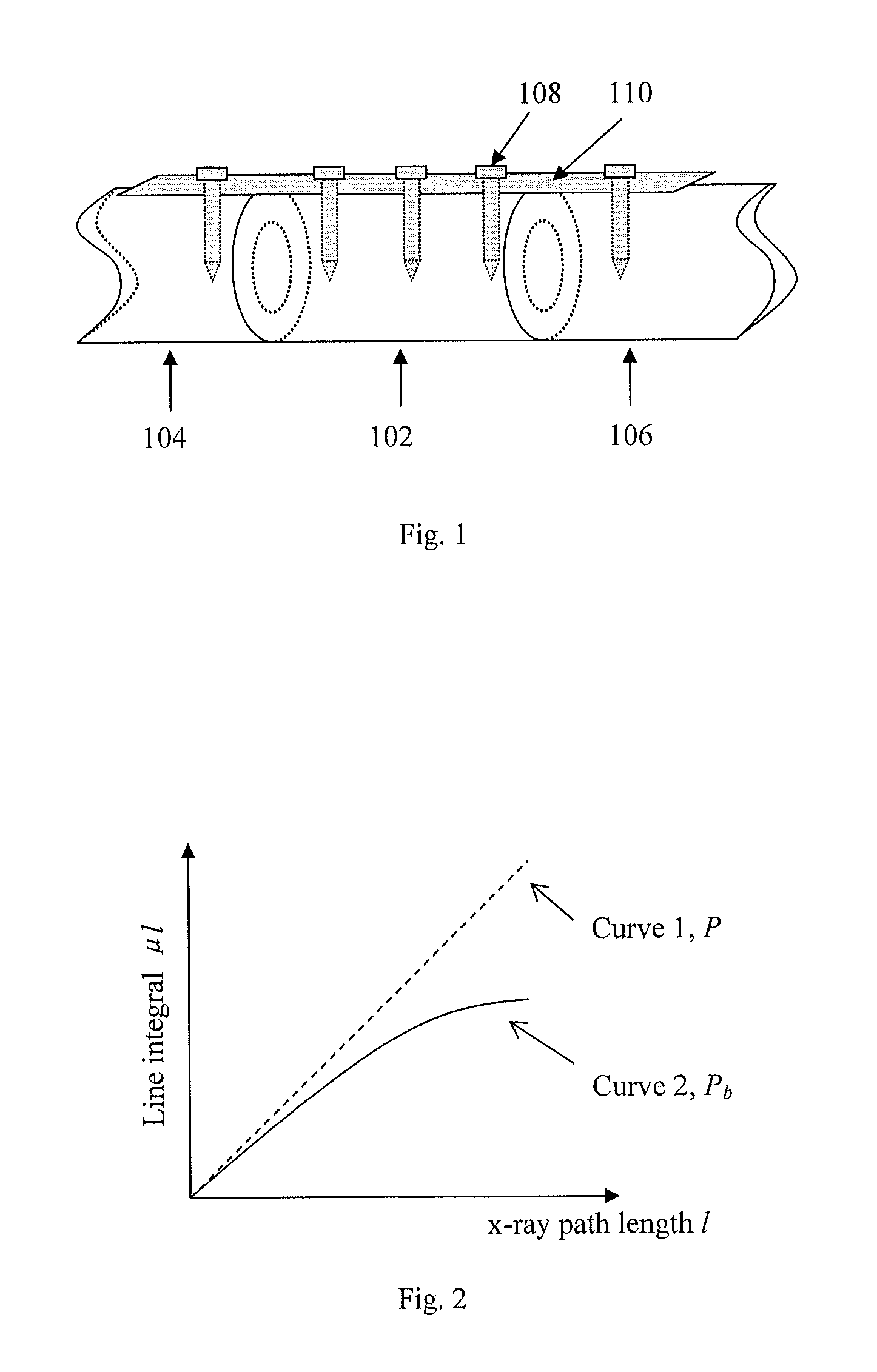
[0020]Metal artifacts are mainly due to the beam hardening caused by high attenuation of x-rays of metal implants. Because more low-energy photons are absorbed by metal, the x-ray beam becomes more penetrating and thus the attenuation coefficient of the object along the x-ray path appears smaller and smaller along the x-ray path. Therefore, the line integral is not linear to the length of the x-ray path anymore. Instead, it gets smaller as the x-ray path gets longer, as illustrated in FIG. 2.

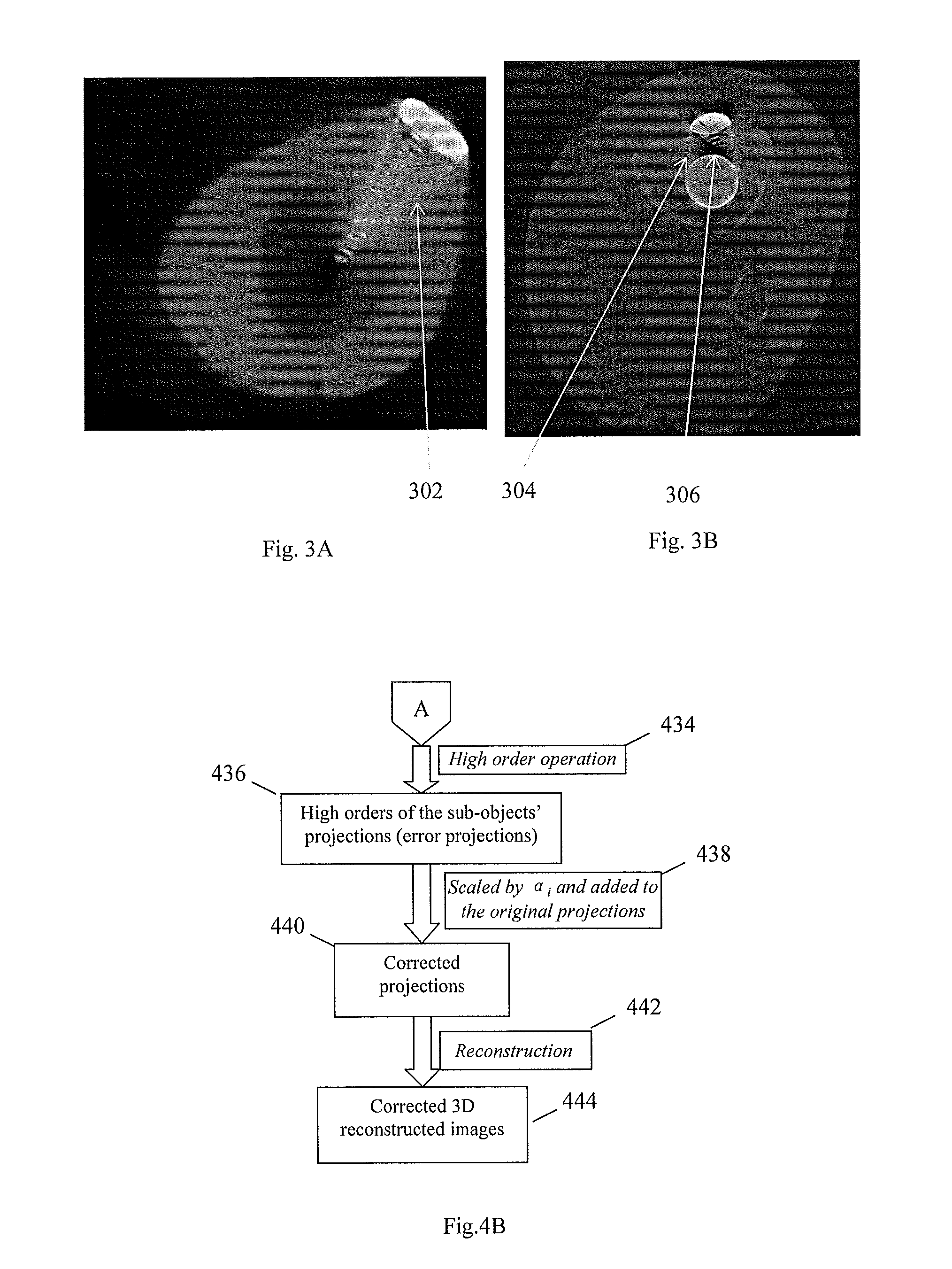
[0021]Since there are discrepancies between the projection rays that pass through only one of the dense objects and the rays that pass through multiple objects, dark banding artifacts and streaking artifacts appear, as seen in FIGS. 3A and 3B, which show streaking artifacts 302 and 304 and shading artifacts 3...


PUM


Abstract

A 3D metal artifacts correction technique corrects the streaking artifacts generated by titanium implants or other similar objects. A cone-beam computed tomography system is utilized to provide 3D images. A priori information (such as the shape information and the CT value) of high density sub-objects is acquired and used for later artifacts correction. An optimization process with iterations is applied to minimize the error and result in accurate reconstruction images of the object.

Description

REFERENCE TO RELATED APPLICATION[0001]The present application is a continuation of U.S. patent application Ser. No. 12 / 045,552, filed Mar. 10, 2008, currently pending, whose disclosure is hereby incorporated by reference in its entirety into the present disclosure.STATEMENT OF GOVERNMENT INTEREST[0002]The work leading to the present invention was funded by the NIH under Agreement Nos. R01 9 HL078181 and P50 AR054041. The government has certain rights in the invention.FIELD OF THE INVENTION[0003]The present invention is directed to CT imaging and more particularly to the correction of high-density artifacts in such imaging.DESCRIPTION OF RELATED ART[0004]Bone grafting is a common procedure in orthopedic surgery. As shown in FIG. 1, a bone graft 102 is grafted between bone hosts (portions of the patient's original bone) 104 and 106. The bone graft 102 is held in place by a titanium plate 108 and titanium screws 110 until the bone graft 102 and the bone hosts 104, 106 grow together.[00...

Claims


Application Information

Patent Timeline
Patent Type & Authority Applications(United States)
IPC IPC(8): G06K9/40G06K9/00
CPCA61B6/032G06T2207/30052A61B6/4233A61B6/488A61B6/505A61B6/5205A61B6/5258A61B6/563G06T7/0083G06T7/0089G06T11/005G06T2207/10081G06T2207/20128G06T2207/30008A61B6/4085G06T7/12G06T7/149
Inventor NING, RUOLAZHANG, YAN
Owner UNIVERSITY OF ROCHESTER
Why Eureka
Try Eureka