
Reducing noise and artifacts in an image

a technology of noise and artifacts, applied in the field can solve the problems of blockage and ringing, correlated luminance and chrominance errors, and traditional digital images from low resolution sources, and achieve the effects of reducing noise and artifacts in images

Inactive Publication Date: 2011-01-11
HEWLETT PACKARD DEV CO LP
View PDF6 Cites 11 Cited by
  • Summary
  • Abstract
  • Description
  • Claims
  • Application Information

AI Technical Summary

Benefits of technology

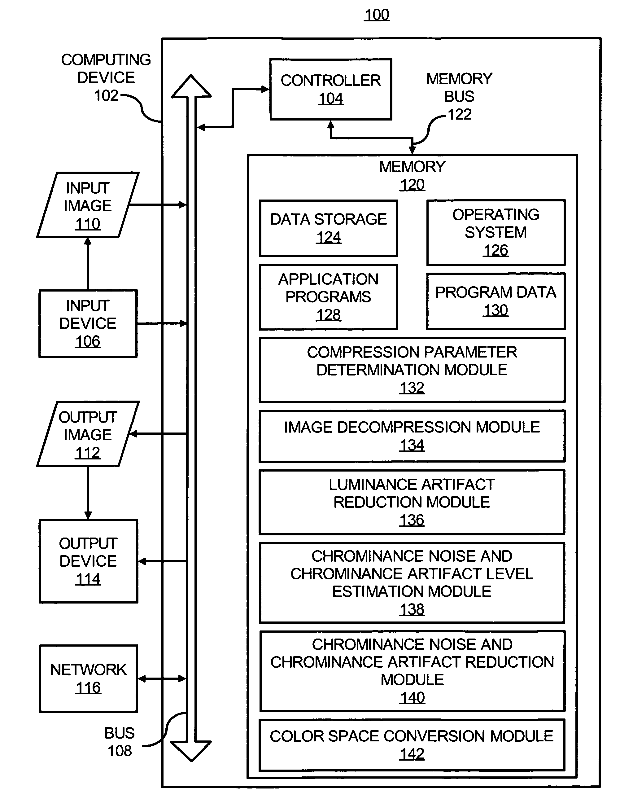
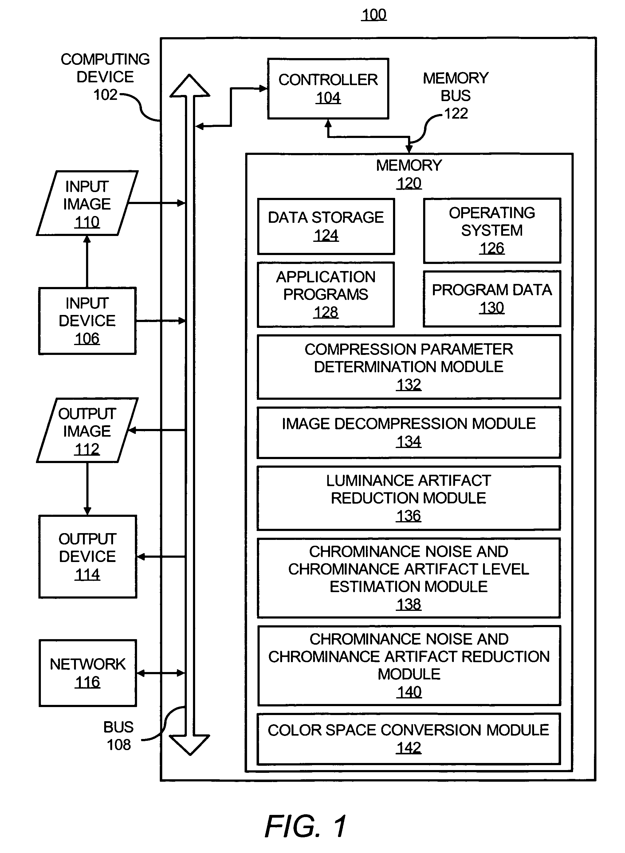
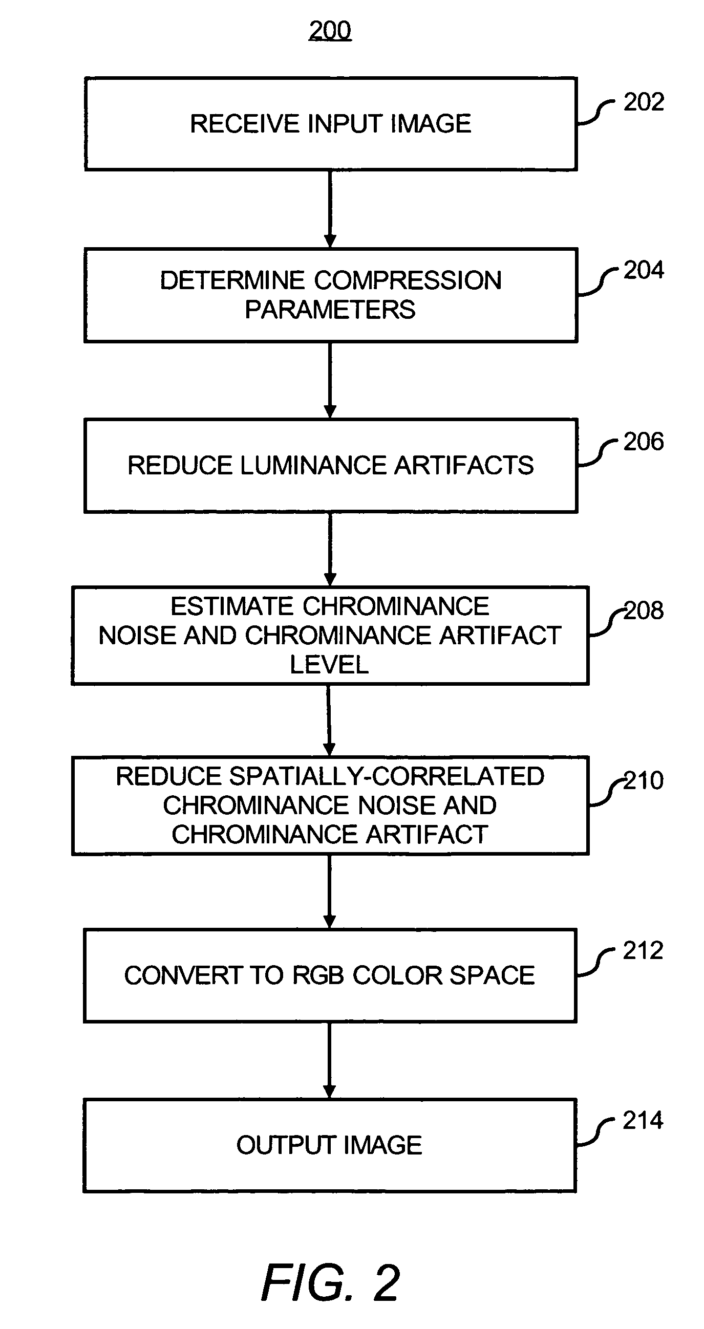
[0011]An input image may include one or both of compression artifacts and image noise. As described in greater detail herein below, the input image may be processed in various respects to substantially reduce or eliminate both of the compression artifacts and the image noise. In one regard, the input image may be processed such that the artifacts are reduced in the luminance channel and the image noise and artifacts are reduced in the chrominance channel. In addition, the artifact reduced luminance channel may operate as guidance for multi-resolution luminance-guided filtering of the chrominance channel.
[0012]The techniques disclosed herein are operable to reduce relatively high noise and artifacts in the chrominance channels by using the artifact reduced luminance channel as guidance for multi-resolution filtering in the chrominance channel. Thus, the chrominance noise and artifact may be reduced in a relatively aggressive manner substantially without blurring the image and may rely on relatively less accurate noise estimation techniques. The techniques disclosed herein may also be relatively robust to the errors in the noise variance estimation since these estimates may only be used to reduce chrominance noise and chrominance artifacts, where errors in the estimates are not as visible as they would be in the luminance channel. In addition, these techniques may be relatively robust to the estimation of compression parameters since these estimates may only be required for the luminance component artifact reduction.
[0013]Generally speaking, the compression artifact reduction parameters required in the luminance channel are fairly robust. In certain examples, the parameters are directly derived from compression parameters directly available from digital image files. Even in cases where the compression parameters require estimation, the parameters are simpler to estimate than chrominance compression parameters because there is no subsampling in the luminance components, and the quantization factors are typically smaller, making their estimation easier.
[0014]Also disclosed herein is an architecture that concurrently reduces compression artifacts and image noise. The combination is performed in a way that alleviates weaknesses of singularly applying either compression artifact reduction or image noise reduction. According to an example, the blocks for compression artifact reduction and image noise reduction may: 1) reduce compression artifacts effectively by processing only the luminance channel and 2) reduce the high noise and artifacts in the chrominance channel by using the artifact reduced luminance channel as guidance for multi-resolution noise filtering (in other words, the chrominance noise and chrominance artifact reduction may be more aggressive without blurring the image and may rely less on accurate noise estimation). In addition, the techniques disclosed herein are more robust to errors in the noise variance estimation since these estimates are used only to reduce chrominance noise and chrominance artifacts and are more robust to estimation of compression parameters (required by some architectures) since they are only needed for the luminance component as compared with known image enhancement techniques.

Problems solved by technology

Traditional digital images from low resolution sources, such as, cellular telephones, personal digital assistants and web sites typically have both compression artifacts and image noise.
The compression artifacts often produce blocks and ringing, and the image noise often results in correlated luminance and chrominance errors.
Images that contain both compression artifacts together with image noise are much harder to enhance than images containing only a single type of degradation.
This is because estimating image noise levels is difficult for low-resolution images, and erroneous noise estimates in the luminance channel often result in insufficient luminance noise reduction or overly blurred images, and artifact reduction alone does not sufficiently reduce the strong chrominance noise (which is not necessarily due to compression) that is typically observed with these images.
In comparing the lower resolution images obtained from the above-described low resolution sources with higher resolution images, the lower resolution images typically have higher noise due to low quality CMOS image sensors.
In addition, the lower resolution capture devices typically have lower cost, and hence lower quality optics, and often have a relatively high compression ratio.
As such, the lower resolution images often have a relatively large number of visually objectionable artifacts, especially for images obtained in low light situations, which are typically more clearly visible when the images are enlarged.
However, conventional aggressive linear filtering techniques often resulted in the introduction of visible saturation variations or excessive de-saturation of the image.
Other challenges to conventional image enhancement techniques for low resolution images include the fact that many artifact reduction methods do not work reasonably well for chrominance channels because chrominance noise and artifact are not due solely to compression artifacts, but due to other image noise sources, and they are found to be extremely high for many of the low-resolution images.
In addition, it is often relatively difficult to estimate the amount of noise and hence the denoising parameters for relatively small images.
Moreover, estimating chrominance channel compression parameters is typically much more difficult than the luminance channel because of unknown subsampling factors and higher compression settings for chrominance.

Method used


Image

  • Reducing noise and artifacts in an image
  • Reducing noise and artifacts in an image
  • Reducing noise and artifacts in an image

Examples


Embodiment Construction

iment of the invention; and

[0009]FIG. 4 illustrates a computer system, which may be employed to perform various functions described herein, according to an embodiment of the invention.

DETAILED DESCRIPTION

[0010]For simplicity and illustrative purposes, the present invention is described by referring to embodiments thereof. In the following description, numerous specific details are set forth in order to provide a thorough understanding of the present invention. It will be apparent however, to one of ordinary skill in the art, that the present invention may be practiced without limitation to these specific details. In other instances, well known methods and structures have not been described in detail so as not to unnecessarily obscure the present invention.

[0011]An input image may include one or both of compression artifacts and image noise. As described in greater detail herein below, the input image may be processed in various respects to substantially reduce or eliminate both of t...


PUM


Abstract

In a method of processing an input image, compression parameters of the input image are determined and luminance artifacts in the input image are reduced to obtain an improved luminance component of the input image, where the determined compression parameters guide the luminance artifact reduction. In addition, a chrominance noise and chrominance artifact level of the input image is estimated and a spatially-correlated chrominance noise and chrominance artifact of the input image is reduced with the improved luminance component, where the estimated chrominance noise and chrominance artifact level guide the spatially-correlated chrominance noise and chrominance artifact reduction to obtain an improved chrominance component of the input image. Moreover, an output image having the improved luminance component and the improved chrominance component is outputted.

Description

BACKGROUND[0001]Traditional digital images from low resolution sources, such as, cellular telephones, personal digital assistants and web sites typically have both compression artifacts and image noise. The compression artifacts often produce blocks and ringing, and the image noise often results in correlated luminance and chrominance errors. Images that contain both compression artifacts together with image noise are much harder to enhance than images containing only a single type of degradation. This is because estimating image noise levels is difficult for low-resolution images, and erroneous noise estimates in the luminance channel often result in insufficient luminance noise reduction or overly blurred images, and artifact reduction alone does not sufficiently reduce the strong chrominance noise (which is not necessarily due to compression) that is typically observed with these images.[0002]In comparing the lower resolution images obtained from the above-described low resolutio...

Claims


Application Information

Patent Timeline
Patent Type & Authority Patents(United States)
IPC IPC(8): H04N5/21H04N1/58
CPCH04N1/58H04N9/646H04N9/77H04N19/86H04N19/186H04N19/44H04N19/85H04N19/117
Inventor SAMADANI, RAMINLIM, SUK HWAN
Owner HEWLETT PACKARD DEV CO LP
Learn More