
Image forming method, two-component developer, image forming apparatus and process cartridge

a technology of image forming and two components, applied in the direction of electrographic processes, electrographic processes using charge patterns, instruments, etc., can solve the problems of inability to produce a small number of prints, deterioration of the toner, and deterioration of the charging ability of the carrier

Inactive Publication Date: 2012-01-12
RICOH KK
View PDF5 Cites 18 Cited by
  • Summary
  • Abstract
  • Description
  • Claims
  • Application Information

AI Technical Summary

Benefits of technology

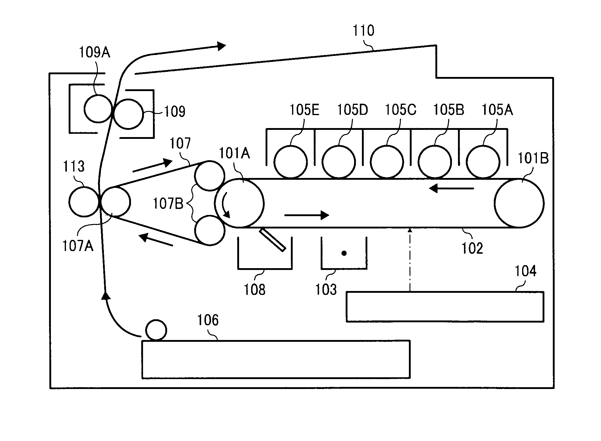
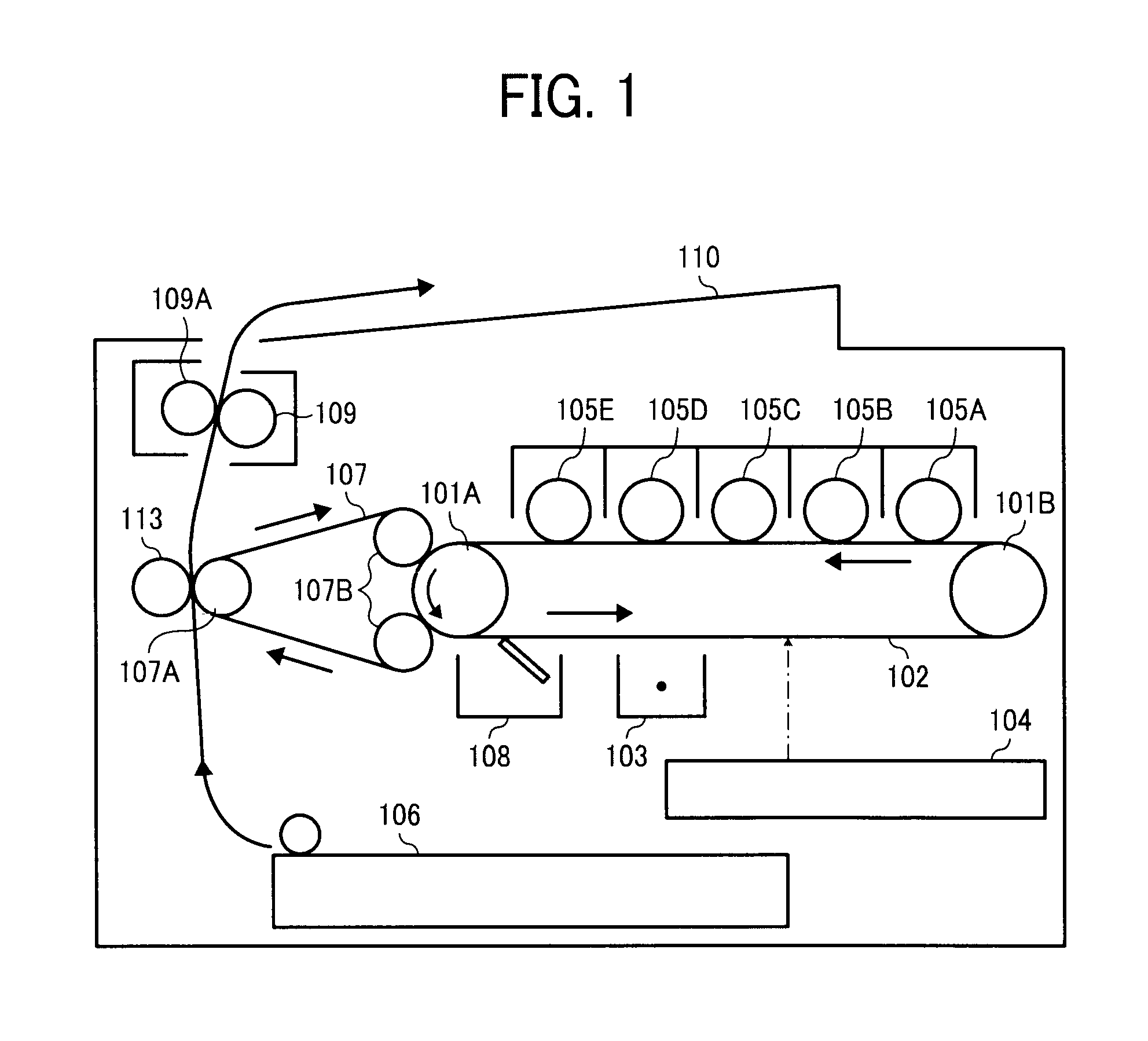
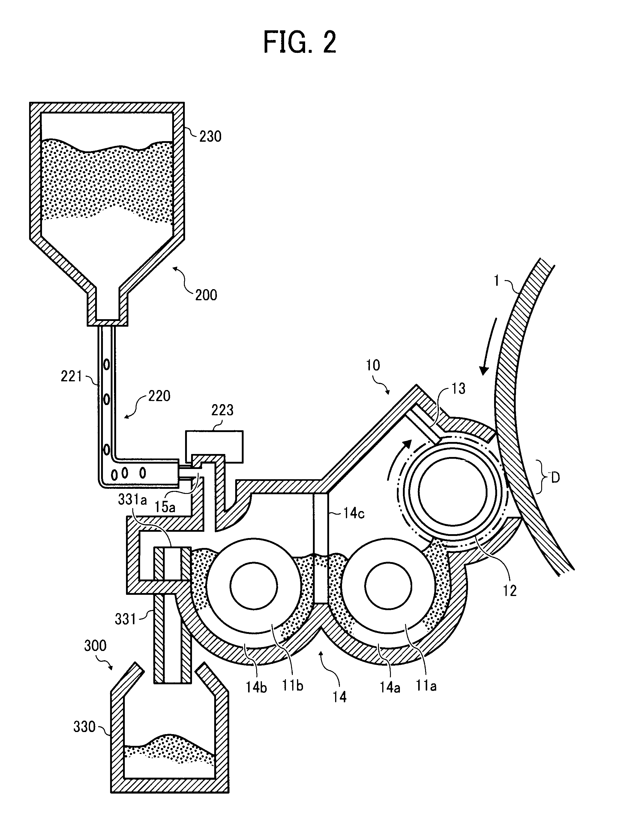
[0021]This patent specification describes a novel image forming method of producing at least one color toner image and a transparent toner image on a recording material. The image forming method uses a first developing device which develops an electrostatic latent image with a first developer including a color toner and a carrier including a core material and a cover layer located on the core material to form the color toner image, and a second developing device which develops an electrostatic latent image with a second developer including a transparent toner and the carrier or another carrier including a core material and a cover layer located on the core material to form the transparent toner image. The color toner image and the transparent toner image are transferred onto the recording material so as to be partially or entirely overlapped, and then the toner images are fixed to the recording material. The image forming method uses a trickle developing method, in which a supplementary developer including the transparent toner and the carrier is supplied to a developing device while excess of the developer in the developing device is discharged, at least for the second developing device. Further, the transparent toner includes a resin and a lubricant, and has a viscoelastic property such that a loss tangent (tan δ), which is defined as a ratio (G″ / G′) of loss modulus (G″) thereof to storage modulus (G′) thereof, has a peak at a temperature of from 80° C. to 160° C. and the peak has a height of not less than 3.

Problems solved by technology

However, when a low temperature fixable toner is prepared merely by decreasing the melting point of the toner, the toner tends to cause a problem in that the preservability of the toner deteriorates.
In addition, when the toner is used for a two-component developer in combination with a carrier, the toner tends to cause a spent toner problem in that the toner adheres to the surface of the carrier when the developer is agitated in a developing device, thereby deteriorating the charging ability of the carrier.
However, when such a print is produced using an offset printing method, it is necessary to prepare an additional plate for forming such a glossy portion.
In addition, this method cannot be used for producing a small number of prints due to increase of running costs, i.e., the method can be used only for producing a large number of prints.
However, in general two-component developing devices, toner is consumed for developing electrostatic latent images while carrier remains in the developing devices without being consumed.
Therefore, the carrier is continuously agitated with toner particles in the developing devices, and the carrier tends to degrade as the agitation period is lengthened.
Specifically, a problem in that a resin layer formed on the surface of the carrier (coated carrier) is peeled therefrom and the spent toner problem in that the toner is adhered to the surface of the carrier are caused.
As a result, the electric resistance of the carrier decreases, and the charge of the developer (toner) decreases (i.e., the developing property of the developer is excessively enhanced), resulting in occurrence of a background development problem in that the background of images is soiled with toner particles, and / or formation of images having an excessively high image density.
However, even when such a trickle developing device is used, the ratio of degraded carrier particles increases as the developer in the developing device is used over a long period of time.
Therefore, it is difficult for the developing device to prevent occurrence of the above-mentioned problems such as the background development problem and the excessively high image density problem.
However, in these methods, the amount of the replaced carrier changes depending on the toner consumption, and therefore the ratio of the fresh carrier in the carrier in the developing device always changes, resulting in change of the resistance or charge imparting ability of the carrier in the developing device, thereby causing the above-mentioned problems such as the background development problem and the excessively high image density problem.
However, it is difficult to sequentially supply the several kinds of supplementary developers contained in the container to a developing device without mixing of the developers.
In addition, the amount of the toner included in each developer is relatively large, and therefore the carrier tends to easily degrade, resulting in variation of image qualities when images are produced by the developing method over a long period of time.
Further, when the weight of a silicone resin cover layer formed on the surface of particles of a carrier used for the developing method is increased to increase the electric resistance of the carrier, the charge imparting ability of the carrier deteriorates although the electric resistance thereof is increased, thereby deteriorating the image qualities (such as image reproducibility) and / or causing the background development problem.
The above-mentioned proposals have been made for a development operation using a color toner, and are not made for a development operation which uses a transparent toner to produce a glossy image portion while reducing the fixing energy and which involves a risk of causing the above-mentioned spent toner problem (i.e., a risk of deteriorating the charge imparting ability of the carrier).

Method used


Image

  • Image forming method, two-component developer, image forming apparatus and process cartridge
  • Image forming method, two-component developer, image forming apparatus and process cartridge
  • Image forming method, two-component developer, image forming apparatus and process cartridge

Examples


example 1

(1) Preparation of Developers

[0243]The following components were mixed.

Transparent toner 1 5 partsCoated ferrite carrier95 parts

[0244]The mixture was mixed for 5 minutes using a TURBULA MIXER mixer from Willy A. Bachofen AG (WAB), which was rotated at a revolution of 48 rpm, to charge the toner.

[0245]Thus, a developer T1 including the transparent toner 1 was prepared.

[0246]The procedure for preparation of the developer T1 was repeated except that the transparent toner 1 was replaced with the black toner 1, the magenta toner 1, the cyan toner 1 or the yellow toner 1 to prepare black, magenta, cyan and yellow developers K1, M1, C1 and Y1.

(2) Preparation of Supplementary Developers

[0247]The following components were mixed.

Transparent toner 180 partsCoated ferrite carrier20 parts

[0248]The mixture was mixed for 5 minutes using a TURBULA MIXER mixer from Willy A. Bachofen AG (WAB), which was rotated at a revolution of 48 rpm, to charge the toner.

[0249]Thus, a supplementary developer TS1 i...

example 2

[0266]The procedure for preparation and evaluation of the developers in Example 1 was repeated except that the transparent toner 1 was replaced with the transparent toner 3.

example 3

[0270]The procedure for preparation and evaluation of the developers in Example 1 was repeated except that the solid transparent toner image was initially formed on the recording material and then a solid color toner image was formed thereon (i.e., the positions of the transparent toner image and a color toner image are reversed).


PUM

PropertyMeasurementUnit
temperatureaaaaaaaaaa
thicknessaaaaaaaaaa
temperatureaaaaaaaaaa

Abstract

In the image forming method, at least one color toner image and a transparent toner image are formed using a color developer including a color toner and a carrier and contained in a first developing device, and a second developer including a transparent toner and a carrier and contained in a second developing device. A supplementary developer is supplied at least to the second developing device while discharging excess of the developer in the developing device. The transparent toner includes a lubricant and has a viscoelastic property such that a loss tangent (tan δ), which is defined as a ratio (G″ / G′) of loss modulus (G″) to storage modulus (G′), has a peak at a temperature of from 80° C. to 160° C. and the peak has a height of not less than 3.

Description

BACKGROUND OF THE INVENTION[0001]1. Field of the Invention[0002]The present invention relates to an image forming method for forming at least one color toner image and a transparent toner image. In addition, the present invention also relates to a two-component developer for use in the image forming method. Further, the present invention relates to an image forming apparatus and a process cartridge using the image forming method.[0003]2. Description of the Related Art[0004]Electrophotographic image forming methods used for dry image forming apparatuses such as laser printers, copiers and facsimiles typically include the following processes:(1) charging the surface of an image bearing member such as a photoreceptor (charging process);(2) irradiating the charged image bearing member with light so that the charges of the irradiated portions decay, thereby forming an electrostatic latent image on the image bearing member (irradiating process);(3) developing the electrostatic latent imag...

Claims


Application Information

Patent Timeline
Patent Type & Authority Applications(United States)
IPC IPC(8): G03G9/00G03G13/22G03G21/18G03G15/01
CPCG03G9/0821G03G9/08755G03G9/08782G03G15/0194G03G9/113G03G15/6585G03G9/1075
Inventor NAGAYAMA, MASASHIAOKI, MITSUOSANTO, HIDEYUKIYAGUCHI, SHIGENORI
Owner RICOH KK
Learn More