Medical devices having flexible electrodes mounted thereon

a technology of flexible electrodes and medical devices, applied in the field of medical devices, can solve the problems of increasing the time of surgery, unable to see the sheath and/or its position, and difficulty in visualizing the sheath and/or its position, and unable to achieve the effect of regaining access

Inactive Publication Date: 2012-01-12
ST JUDE MEDICAL ATRIAL FIBRILLATION DIV
View PDF4 Cites 78 Cited by
  • Summary
  • Abstract
  • Description
  • Claims
  • Application Information

AI Technical Summary

Benefits of technology

[0018]In accordance with an aspect of the present disclosure, a catheter apparatus comprises an elongated body having a distal end, a proximal end, and at least one fluid lumen extending longitudinally therein; and a plurality of flexible electrode segments on a distal portion of the elongated body adjacent the distal end, each pair of neighboring flexible electrode segments being spaced from each other longitudinally by a corresponding electrically nonconductive segment. Each flexible electrode segment comprises a sidewall provided with one or more elongated gaps extending through the sidewall, the one or more elongated gaps providing flexibility in the sidewall for bending movement relative to a longitudinal axis of the catheter body.

Problems solved by technology

One drawback to conventional sheaths and their use is that visualization of the sheath and / or its position has proved difficult, if not impossible.
As a result, physicians have been unable to see the sheath and / or its position during the performance of a medical procedure without the use of ionizing radiation (e.g., acute x-ray delivery via a fluoroscope).
Accordingly, if the physician loses visual contact with a device or the transseptal access is interrupted due to, for example, patient movement or the manipulation of a medical device used with the sheath, regaining access increases the procedure time and also can require another puncture of the septum.

Method used


Image

  • Medical devices having flexible electrodes mounted thereon
  • Medical devices having flexible electrodes mounted thereon
  • Medical devices having flexible electrodes mounted thereon

Examples


Embodiment Construction

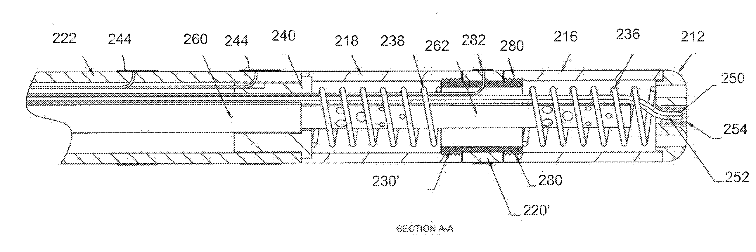
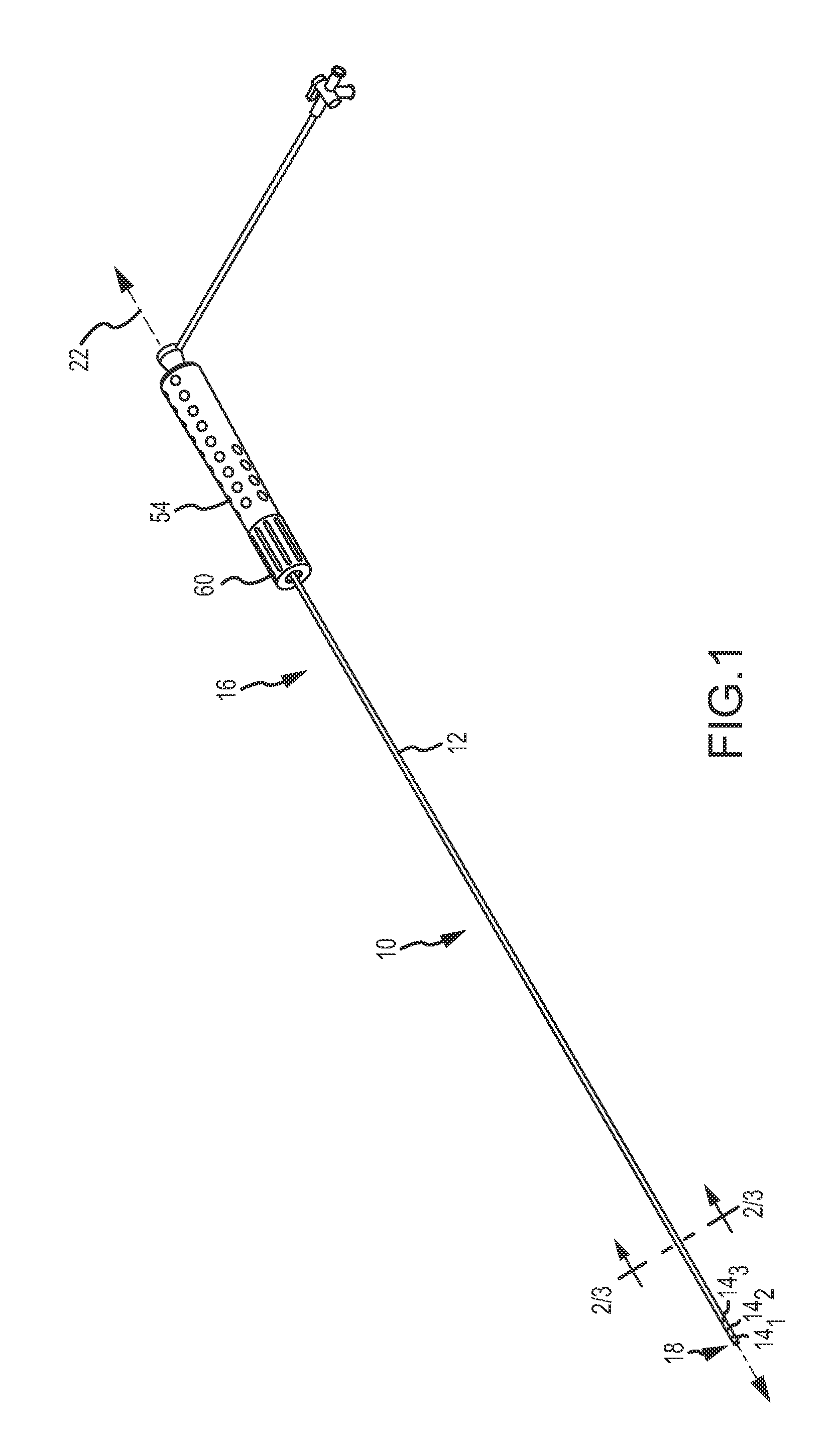
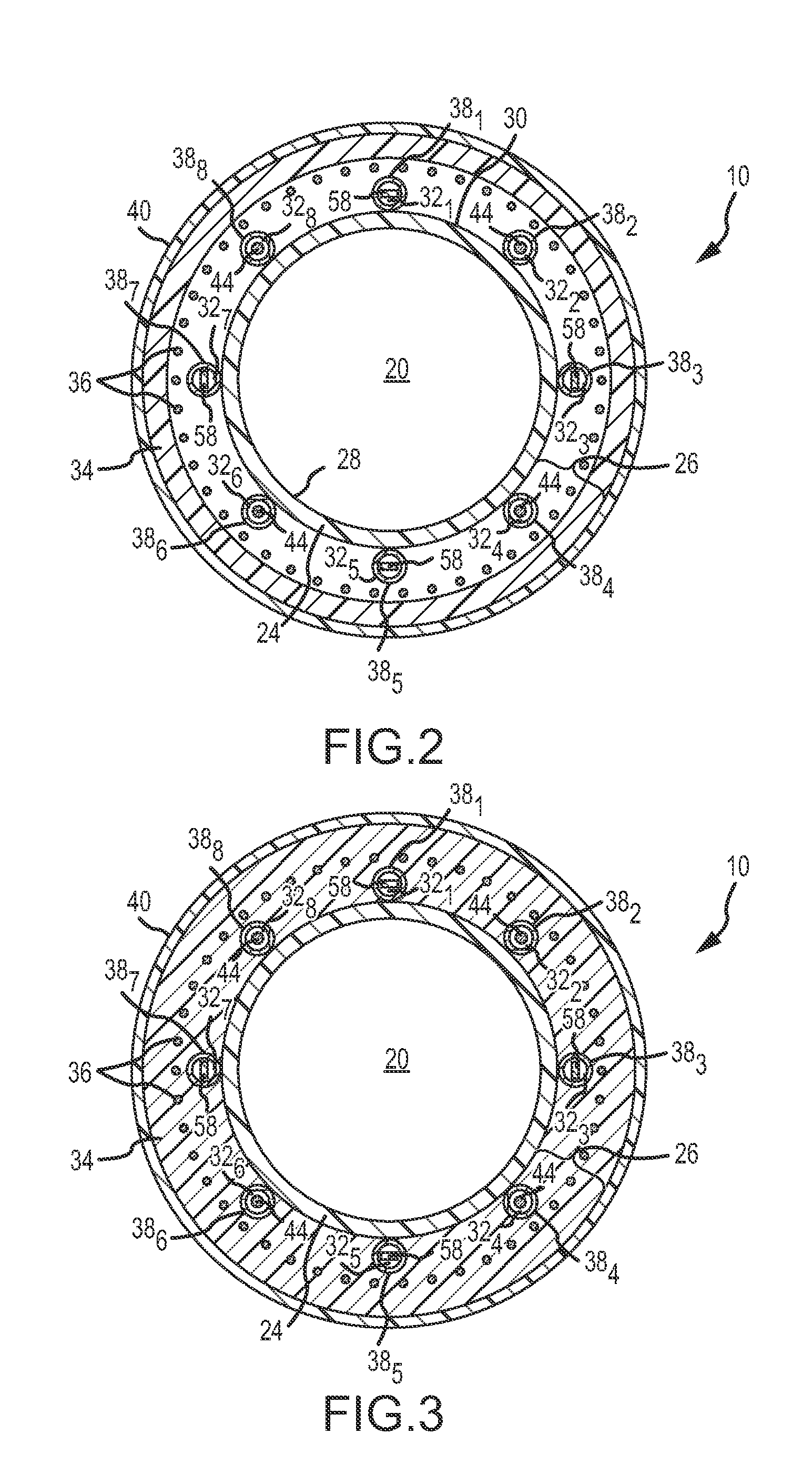
[0036]Referring now to the drawings wherein like reference numerals are used to identify identical components in the various views, FIG. 1 illustrates one exemplary embodiment of a medical device 10, such as, for example and without limitation, a sheath or catheter-introducer for use in connection with a number of diagnostic and therapeutic procedures performed, for example, within the heart of a human being or an animal. For clarity and brevity purposes, the description below will be directed solely to a medical device 10 that comprises a sheath (sheath 10) for use in cardiac applications. It will be appreciated by those having ordinary skill in the art, however, that the description below can be applicable to medical devices other than sheaths, and for sheaths and medical devices used in connection with applications other than cardiac applications. Accordingly, medical devices other than sheaths, and medical devices / sheaths for use in applications other than cardiac applications, ...


PUM


Abstract

Medical devices and systems comprising medical devices are provided. The kit includes a catheter-introducer comprising a shaft having a major lumen sized to receive a second medical device and an electrode mounted thereon and a catheter comprising an elongate body and at least two flexible electrode segments on the distal end. The shaft includes an inner liner and outer layer. The system comprises a first medical device having a shaft and an electroanatomical system imaging element mounted thereon and a second medical device having an elongate body and at least two flexible electrodes mounted on the distal end. The shaft has a major lumen sized to receive the second medical device. The system further comprises an electroanatomical navigation system configured to receive signals from the electroanatomical system imaging element and to determine a position of the electroanatomical system imaging element and / or monitor electrophysiological data.

Description

CROSS-REFERENCE TO RELATED APPLICATIONS[0001]This application is a continuation-in-part of U.S. application Ser. No. 12 / 952,948, filed 23 Nov. 2010 (the '948 application), now pending; and this application claims the benefit of U.S. provisional application No. 61 / 355,242 filed 16 Jun. 2010 (the '242 application). The '948 application and the '242 application are hereby incorporated by reference as though fully set forth herein.BACKGROUND OF THE INVENTION[0002]a. Field of the Invention[0003]This disclosure relates to a family of medical devices. More particularly, this disclosure relates to medical devices, such as, for example, deflectable catheter-introducers or sheaths, having one or more electrodes mounted thereon for electrophysiology (EP) diagnostics and localization and visualization of said devices, as well as methods of manufacturing and systems with which such medical devices are used, including robotic surgical systems.[0004]b. Background Art[0005]It is well known to use a...

Claims


Application Information

Patent Timeline
Patent Type & Authority Applications(United States)
IPC IPC(8): A61B5/05
CPCA61B5/04007A61N1/056A61B5/0536A61B5/0538A61B5/063A61B5/066A61B5/7425A61B18/1492A61B2018/00023A61B2018/00577A61B2019/5251A61B2019/5263A61B2019/5454A61B2019/5466A61B2562/046A61B5/0422A61B2034/2063A61B2034/2051A61B2090/3954A61B2090/3966A61B5/243A61B5/287
Inventor KAUPHUSMAN, JAMES V.FUENTES, ALLAN M.GONZALES, SALOME A.DE LA RAMA, ALANHATA, CARYGRASSE, MARTIN M.
Owner ST JUDE MEDICAL ATRIAL FIBRILLATION DIV
Why Eureka
Try Eureka