Catheter introducer system for exploration of body cavities

a technology of introducers and catheters, applied in the field of catheter introducers, can solve the problems of small working channel, limited current endoscope technology, and small working channel relative to overall diameter, and achieve the effect of less discomfort for patients and convenient us

Inactive Publication Date: 2007-02-06
BOSTON SCI SCIMED INC
View PDF71 Cites 33 Cited by
  • Summary
  • Abstract
  • Description
  • Claims
  • Application Information

AI Technical Summary

Problems solved by technology

However, current endoscope technology has limitations and drawbacks.
One of the greatest drawbacks of current endoscopes is that the working channel is small.
The working channel is small relative to overall diameter of the endoscope, and is further limited by the space taken up by vision, irrigation, suction, light, and control cabling mechanisms that are part of the endoscope and are required to control the endoscope.
Current endoscopes are also difficult to maneuver, particularly when the endoscope has to be pushed from outside the body all the way to a far portion of the intestine, such as the cecum, located at the beginning portion of the large intestine.
Currently, reaching the cecum requires training, skill, luck and trial and error on the part of the operator.
This situation creates an inherently unstable condition, where a long tube is being pushed through a narrow cavity.
This requires the endoscope tube to be rather rigid, resulting in discomfort to the patient as the endoscope is maneuvered.
Current endoscopes tend to be reusable because of the high cost of their components, and thus require thorough cleaning to sterilize them.
Sterilization can be difficult to guarantee, and in many instances a disposable device would be preferable.

Method used


Image

  • Catheter introducer system for exploration of body cavities
  • Catheter introducer system for exploration of body cavities
  • Catheter introducer system for exploration of body cavities

Examples


first embodiment

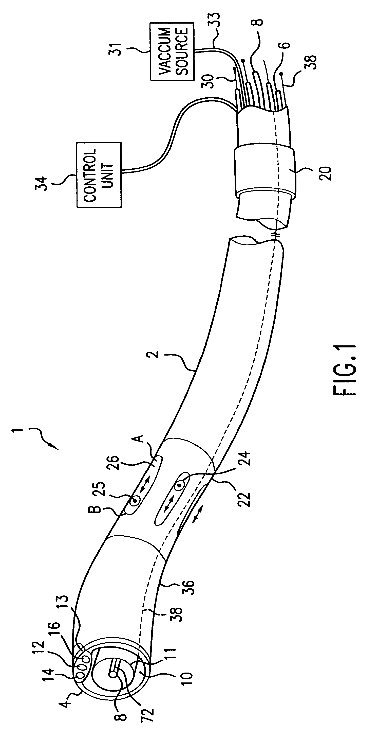
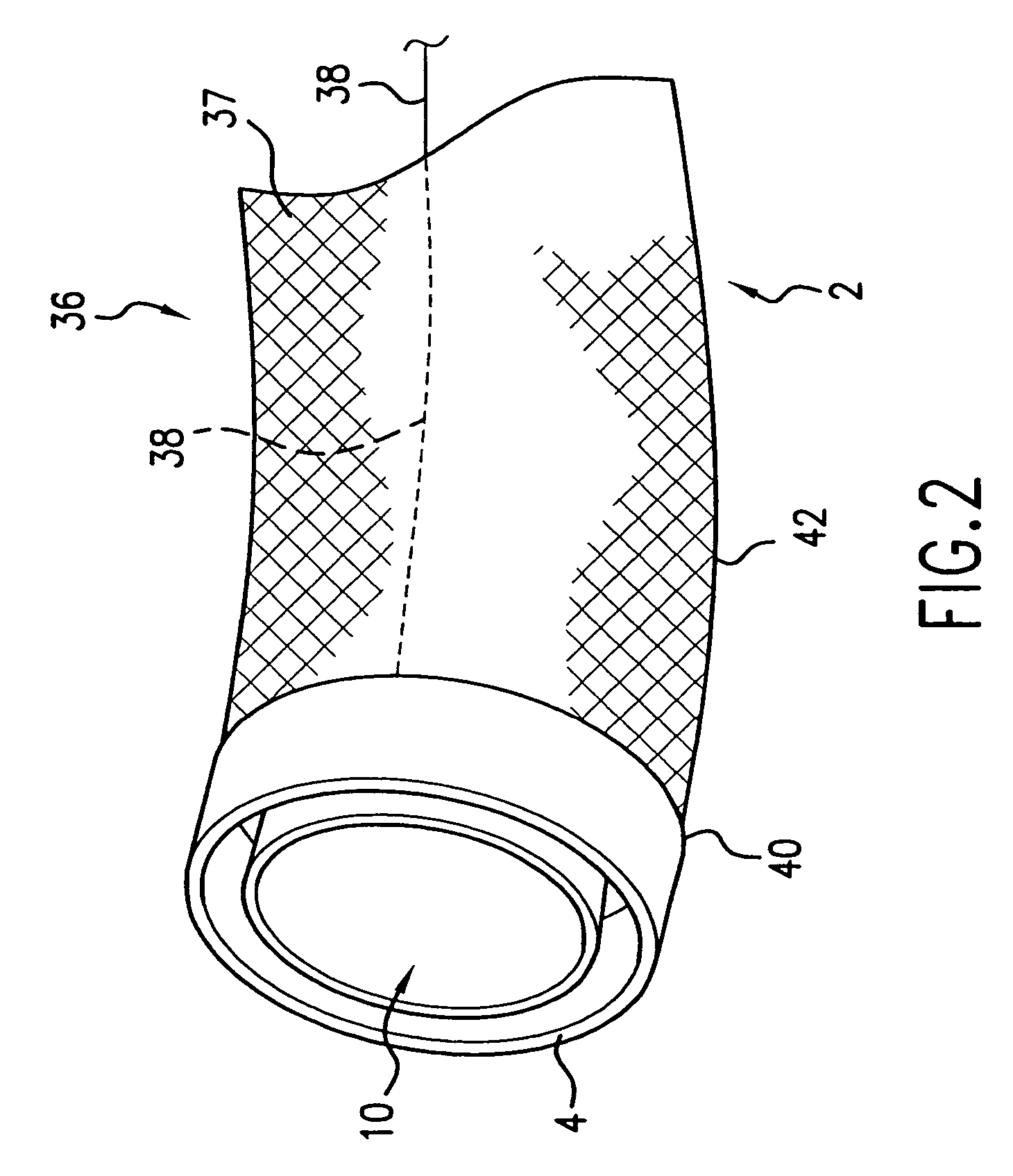
[0043]FIG. 1 illustrates the endoscopy delivery catheter according to the invention. Catheter introducer system 1 includes a flexible tubular catheter 2 having a distal end 4 and a proximal end 6. Distal end 4 is the end of the catheter that is introduced in the body cavity, while proximal end 6 is at the opposite end from distal end 4 and remains outside of the body cavity. Flexible catheter 2 is hollow on the inside, thus defining a working channel 10 that extends from proximal end 6 to distal end 4. Since the catheter 2 is very flexible, it can have a large diameter, so that a large working channel 10 is provided for introduction and maneuvering of endoscopy tools 8.

[0044]In a preferred embodiment, the working channel is defined by a sheath 11, which is non-collapsible and thus tends to maintain a circular cross section even when it is bent along its axis. Sheath 11 can also include a coil to help maintain its cross sectional shape. The working channel tends to retain a constant ...

second embodiment

[0068]FIG. 3 shows the catheter introducer system for endoscopy according to the present invention. As shown in FIG. 3, a tube-like catheter 2 defines a working channel 10 and has a distal end 4 designed for introduction in the body cavity. As described above, a resilient sheath 11 can be used to define the working channel 10. Near the distal end 4 of the catheter 2, there is a steering / propulsion section 50 that is used both to pull the rest of the catheter along in the body cavity that is being explored, and also to direct the distal end 4 of the catheter 2 in the desired direction.

[0069]Steering / propulsion section 50 comprises a steering / elongation portion 52 that provides elongation as well as steering functions for the catheter introducer system 1′. For example, steering / elongation portion 52 can be formed by a mesh with push-pull wires similar to the one described in FIG. 2. If the push-pull wires are extended or withdrawn at the same time, steering / elongation portion 52 elong...


PUM


Abstract

A self propelling catheter introducer system for exploring a body cavity is disclosed which includes a flexible tubular catheter, an everting tube and a steering section located near the distal end of the catheter that is introduced in a body cavity. The steering section is adapted for pointing the distal end in a desired direction using a plurality of rods adapted to be extended and retracted.

Description

RELATED APPLICATIONS[0001]This application is a continuation of U.S. patent application Ser. No. 10 / 020,913, filed on Dec. 19, 2001, and now U.S. Pat. No. 6,699,179, which is a continuation in part of U.S. patent application Ser. No. 09 / 492,448, filed on Jan. 27, 2000, and now U.S. Pat. No. 6,517,477.BACKGROUND OF THE INVENTION[0002]The present invention relates to a method and a device for performing endoscopy through a catheter introducer system. In particular, the present invention relates to a catheter introducer system for endoscopy designed to reach the cecum portion of the gastrointestinal tract.DESCRIPTION OF RELATED ART[0003]Endoscopy has become an increasingly important tool in diagnosing and in treating ailments of the gastrointestinal tract, also referred to as the GI tract. Typical endoscopes are essentially formed by a somewhat flexible tube that is pushed through the GI tract, after being introduced in the body cavity starting from the rectum or starting from the esop...

Claims


Application Information

Patent Timeline
Patent Type & Authority Patents(United States)
IPC IPC(8): A61B1/01A61B1/00A61B1/005A61B1/018A61B1/273A61B1/31A61M25/01A61M25/082
CPCA61B1/00156A61B1/0052A61B1/018A61B1/31A61M25/0116A61M25/0119A61B1/053A61B1/0058A61M2210/1042A61B1/2733A61B1/00148
Inventor WENDLANDT, JEFFREY MICHAEL
Owner BOSTON SCI SCIMED INC
Why Eureka
Try Eureka