Magnetic vise

a magnetic and vise technology, applied in the field of magnetic vises, can solve the problems of not fully meeting user requirements, taking a lot of time and effort,

Inactive Publication Date: 2012-01-19
CHIANG WEN HSUAN
View PDF19 Cites 11 Cited by
  • Summary
  • Abstract
  • Description
  • Claims
  • Application Information

AI Technical Summary

Benefits of technology

[0005]Therefore, the primary object of the present invention is to provide a vise wit

Problems solved by technology

It takes a lot of time and effort, and

Method used


Image

  • Magnetic vise
  • Magnetic vise
  • Magnetic vise

Examples


Embodiment Construction

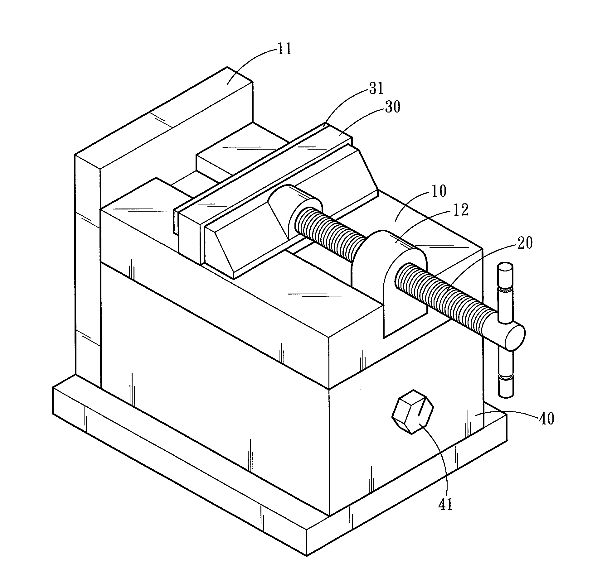
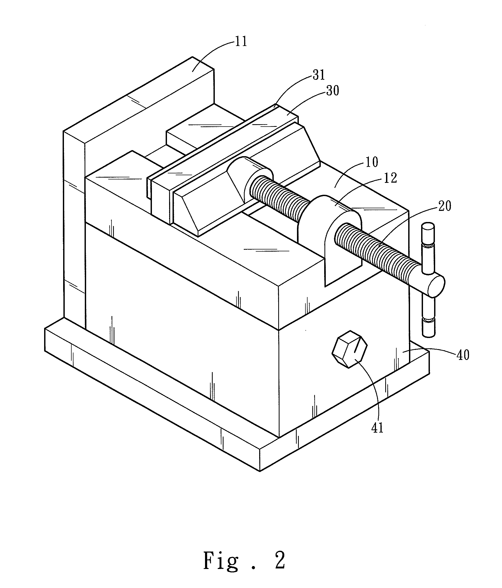
[0013]Please refer to FIG. 2, the present invention provides a magnetic vise which comprises a holder 10, a rotary bar 20, a movable portion 30 and a magnetic portion 40. The holder 10 has a butting surface 11 extended transversely and a boss 12 opposing the butting surface 11. The rotary bar 20 is a turnable screw bar running through the boss 12 and has a distal end latched on the movable portion 30 to push and pull the movable portion 30. The movable portion 30 has a clamping surface 31 facing the butting surface 11. The magnetic portion 40 is located beneath the holder 10 and can be a permanent magnet or electromagnet.

[0014]Also referring to FIG. 3, the magnetic portion 40 provides magnetic force and may be inserted by a magnetic rod 41. The magnetic rod 41 can be turned according to requirements to make the magnetic portion 40 either in a demagnetized state (as shown in FIG. 2) or a magnetized state (as shown in FIG. 3). When the magnetic portion 40 is in the demagnetized state,...


PUM


Abstract

A magnetic vise comprises a holder, a movable portion, a rotary bar and a magnetic portion. The magnetic portion is located beneath the holder. The holder has a butting surface extended transversely and a boss opposing the butting surface. The rotary bar is a turnable screw bar running through the boss and has a distal end latched on the movable portion to push and pull the movable portion. The movable portion has a clamping surface facing the butting surface. A working piece can be positioned on the holder and attracted by the magnetic force of the magnetic portion to be tightly attached to the holder. The rotary bar can be turned to drive the movable portion against the holder so that the clamping surface is moved towards the butting surface to clamp the working piece without skewing during the clamping process.

Description

FIELD OF THE INVENTION[0001]The present invention relates to a magnetic vise and particularly to a magnetic vise to clamp a working piece through aid of magnetic force.BACKGROUND OF THE INVENTION[0002]A conventional vise, referring to FIG. 1, includes a holder 1, a movable portion 2 and a rotary bar 3. The holder 1 has a butting surface 4 extended transversely and a boss 5 opposing the butting surface 4. The rotary bar 3 is a turnable screw bar running through the boss 5 and has a distal end latched on the movable portion 2 to push or pull the movable portion 2. The movable portion 2 has a clamping surface 6 facing the butting surface 4.[0003]To clamp a working piece (not shown in the drawing), dispose the working piece on the holder 1, turn the rotary bar 3 to drive the movable portion 2 relative to the holder 1 and move the clamping surface 6 towards the butting surface 4 to clamp the working piece.[0004]The aforesaid clamping of the working piece relies on the clamping surface 6 ...

Claims


Application Information

Patent Timeline
IPC IPC(8): B25B11/00
CPCB25B1/103B25B11/002B25B1/2484
Inventor CHIANG, WEN-HSUAN
Owner CHIANG WEN HSUAN
Why Eureka
Try Eureka