Traction Device To Walk On Ice While Wearing Ice Skate Scabbard

a technology of traction device and ice skate, which is applied in the field of traction device to walk on ice while wearing ice skate scabbard, can solve the problems of increasing the risk of injury, and achieve the effect of increasing traction and reducing the chance of the wearer falling o

Inactive Publication Date: 2012-01-19
KAPP CONSULTING GROUP
View PDF5 Cites 6 Cited by
  • Summary
  • Abstract
  • Description
  • Claims
  • Application Information

AI Technical Summary

Benefits of technology

[0015]It is an object of the present invention and is a focus of the present application to provide an ice skate scabbard having a traction device that allows a wearer to wear the scabbard while walking on ice that decreases the chance of the wearer suffering a fall and provides increased traction while walking on ice.
[0016]The present invention provides for an abrasive material, such as sandpaper, metal oxide, or grit, to be added to a standard ice skate guard that does not provide sufficient traction on ice for a user. The present invention involves an ice skate scabbard assembly that includes this traction device on the bottom surface of the ice skate scabbard and is able to be worn onto ice without the wearer falling. The present invention prevents the wearer from falling when the wearer forgets to remove the ice skate scabbard before getting on the ice and allows the wearer to actually walk onto the ice and remove the scabbards anywhere on the ice that the wearer wishes. A wearer can also reverse this situation when choosing to exit the ice, by putting on the scabbards while standing on the ice and then walking off the ice.
[0017]The invention allows for the wearer to step out onto the ice and walk on the ice to wherever he or she pleases before removing his / her ice skate scabbards from the ice blades. With the invention, a wearer can walk to the ice in his / her ice skates with scabbards on, may choose to remove the scabbards or not, may step onto the ice, and may move away from the entrance and remove the scabbards. This prevents an unsafe condition at the entrance of an ice rink where multiple skaters are trying to enter the ice simultaneously after stopping to remove their scabbards. In this situation, there is an increased risk of injury.

Problems solved by technology

In this situation, there is an increased risk of injury.

Method used


Image

  • Traction Device To Walk On Ice While Wearing Ice Skate Scabbard
  • Traction Device To Walk On Ice While Wearing Ice Skate Scabbard
  • Traction Device To Walk On Ice While Wearing Ice Skate Scabbard

Examples


Embodiment Construction

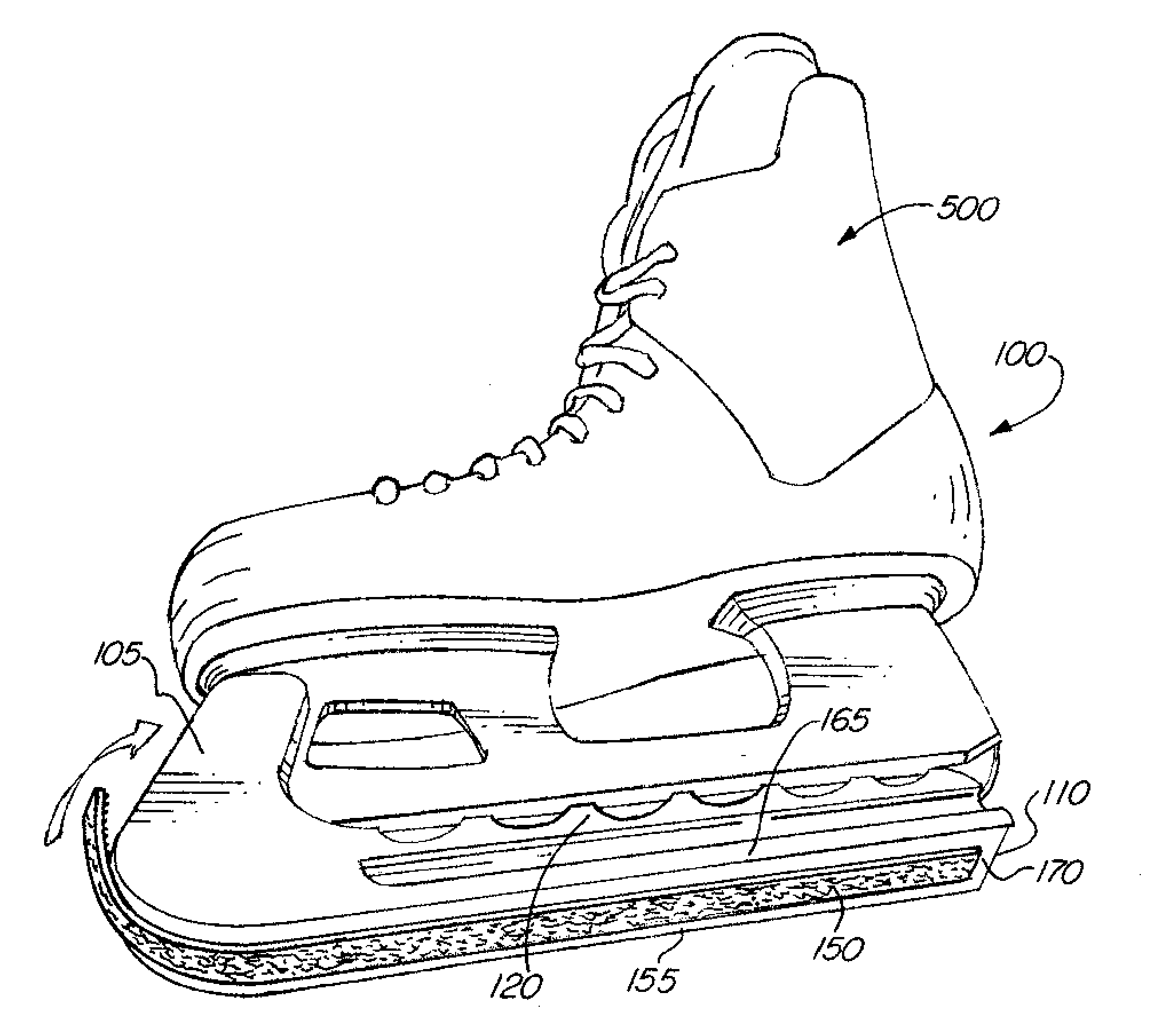
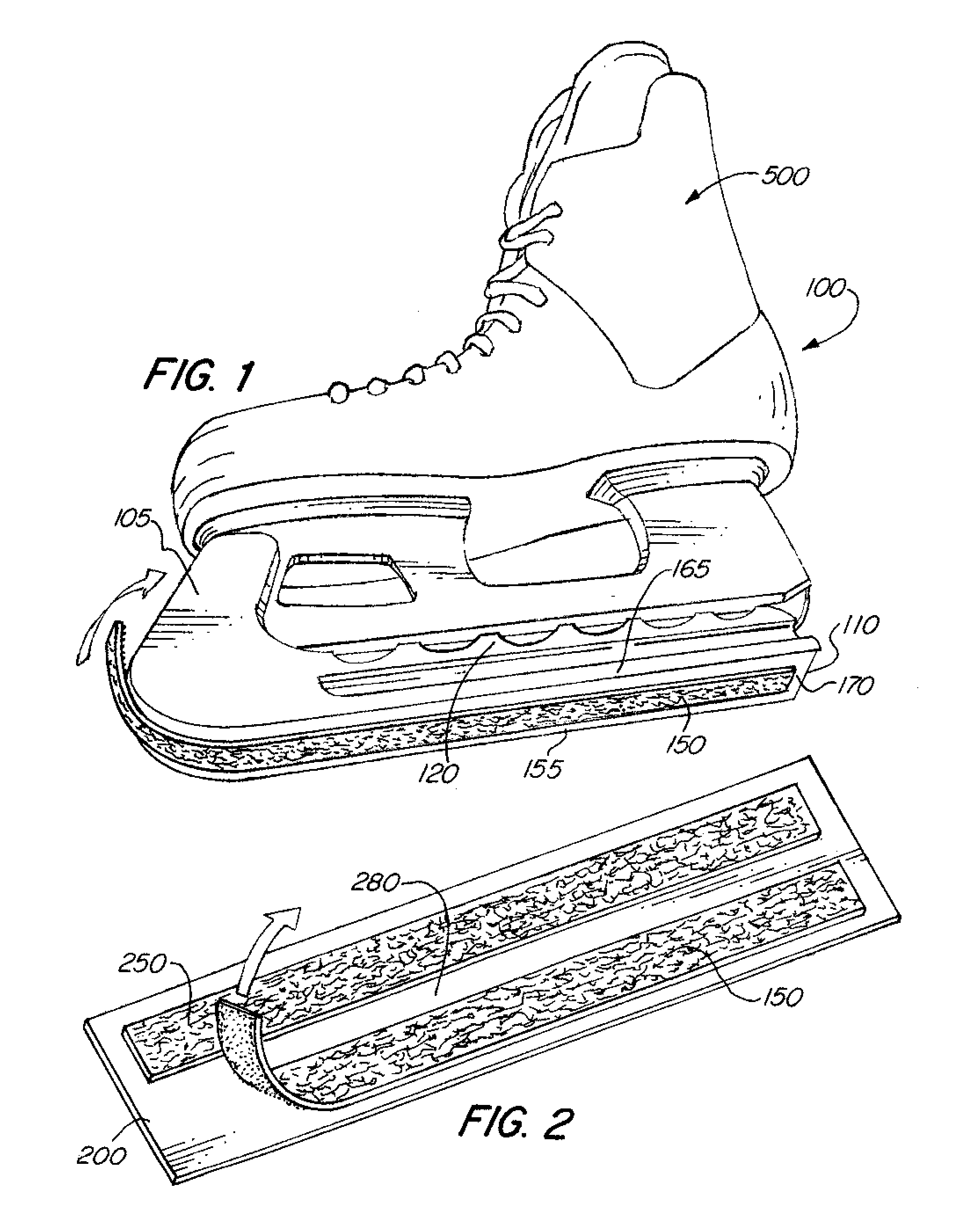
[0058]Referring now to FIG. 1, an ice skate scabbard 100 is shown having at least one traction device 150. Also shown are front end 105, rear end 110 and side end 120 of ice skate scabbard. Side end 125 is not shown. The front end 105 is shown sweeping upwardly away from the bottom end. An ice skate blade 500 is shown and may align with the front end 105 of ice skate scabbard 100, and may fit in an opening between the front end 105, two side ends 120 and 125 and rear end 110 of the ice skate scabbard.

[0059]FIG. 1 also shows spaces 155 and 165 which are between the side ends 120 and 125 and the at least one traction device 150. These spaces are used to prevent fraying of the at least one traction device 150. Furthermore, space 170 is shown between the at least one traction device 150 and rear end 110 of the scabbard, while space 175 is not shown, which is between at least one traction device 150 and front end 105. Space 175 is also for preventing fraying of the at least one traction ...


PUM

PropertyMeasurementUnit
traction/frictionaaaaaaaaaa
frictionaaaaaaaaaa
friction/tractionaaaaaaaaaa

Abstract

An ice skate scabbard assembly or kit including a traction device attached to the bottom of an ice skate scabbard allowing for a wearer to walk onto ice while wearing the scabbard and to provide increased traction / friction, such that the wearer of the ice skate scabbard assembly will not fall while walking onto the ice. The assembly has at least one ice skate scabbard, at least one traction device and at least one attachment element for attaching the at least one ice skate scabbard to the at least one traction device.

Description

CROSS-REFERENCE TO RELATED APPLICATIONS[0001]The present application claims the benefit under 35 U.S.C. §119(e) of the U.S. Provisional Patent Application Ser. No. 61 / 363,853, entitled “Traction Device To Walk On Ice While Wearing Ice Skate Scabbard” filed on Jul. 13, 2010, the content of which is incorporated herein by reference.FIELD OF THE INVENTION[0002]An ice skate scabbard assembly or kit including a traction device attached to the bottom of an ice skate scabbard allowing for a wearer of ice skates to walk on ice while wearing the scabbard and providing increased traction / friction, such that the wearer of the ice skate scabbard assembly will not fall while walking on the ice and will have improved traction / friction on the bottom of the ice skate scabbards as the wearer is walking on the ice.BACKGROUND OF THE INVENTION[0003]Ice skate scabbards protect ice skate blades from being damaged while being carried in a skate bag and also protect a user or wearer of ice skates from bein...

Claims


Application Information

Patent Timeline
Patent Type & Authority Applications(United States)
IPC IPC(8): A63C3/12B23P11/00B32B3/06
CPCA63C3/12Y10T29/49826Y10T428/24008
Inventor KAPP, DOUGLAS
Owner KAPP CONSULTING GROUP
Why Eureka
Try Eureka