Syringe drive device

Inactive Publication Date: 2012-01-19
PANASONIC CORP
View PDF1 Cites 3 Cited by
  • Summary
  • Abstract
  • Description
  • Claims
  • Application Information

AI Technical Summary

Benefits of technology

[0015]In view of the above-described problems, it is an object of the invention to provide a user-friendly syringe drive device which facilitates performing air purge.
[0017]With this structure, to purge air or for other purposes, the user can rotate the cylinder while holding it in one hand. Thus, the syringe drive device is extremely user-friendly.

Problems solved by technology

In this conventional syringe drive device, however, a complex process is required to rotate the cylinder as follows.

Method used


Image

  • Syringe drive device
  • Syringe drive device
  • Syringe drive device

Examples


first embodiment

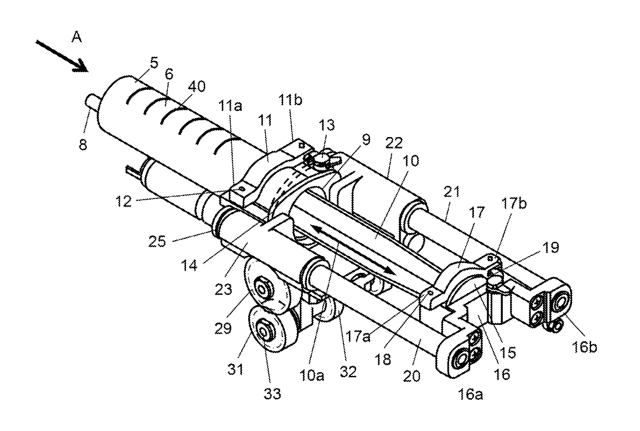
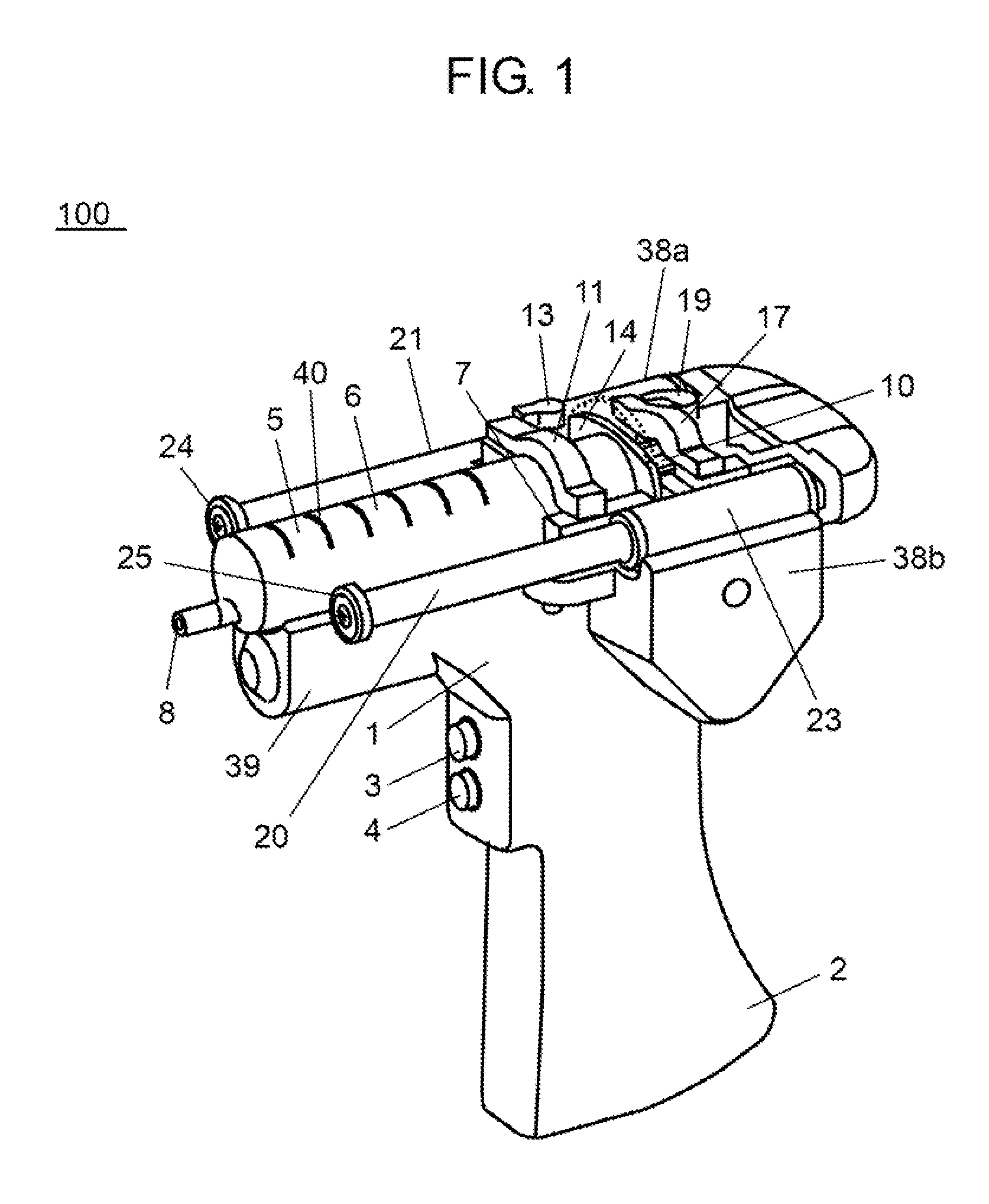
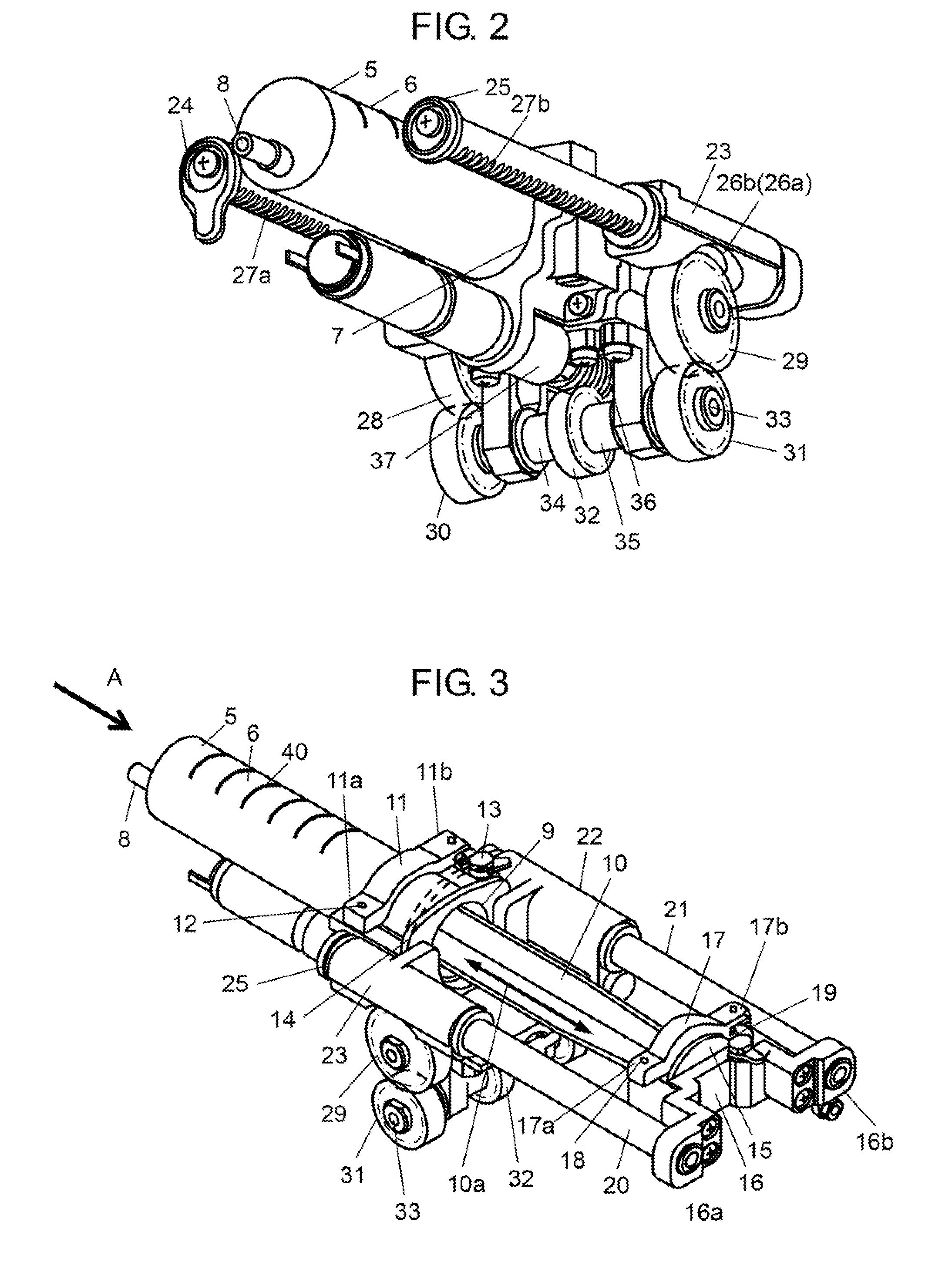
[0032]FIG. 1 is a perspective view of a syringe drive device according to a first embodiment of the invention. FIGS. 2 and 3 are perspective views of first and second examples, respectively, of mechanism elements of the syringe drive device. FIG. 4 shows the syringe drive device viewed from the direction of “A” in FIG. 3.

[0033]FIGS. 2 and 3 show the mechanism elements of syringe drive device 100 where body case 1 and covers 38b, 39 are not illustrated. The description of these drawings is based on the condition that body case 1 and covers 38b, 39 are eliminated.

[0034]In FIG. 1, syringe drive device 100 includes body case 1 and grip 2 at the bottom of body case 1.

[0035]Syringe drive device 100 of the first embodiment is designed to be portable as described above. The user can hold grip 2 in the right hand like holding a pistol, and operate operation buttons 3 and 4 with the index finger placed behind grip 2 in FIG. 1.

[0036]As shown in FIG. 2, syringe drive device 100 further includes...

second embodiment

[0095]In syringe drive device 100 of the first embodiment, the user rotates cylinder 6 by touching its outer periphery. Syringe drive device 200 of a second embodiment of the invention includes operating rod 44 with which the user rotates cylinder 6 as shown in FIGS. 6 and 7. FIG. 6 is a perspective view of mechanism elements of syringe drive device 200, and FIG. 7 is a front view of an essential part of syringe drive device 200. In FIG. 7, hold-down bar 11 is not illustrated so as to clearly show the layout on plane 6A of the outer periphery of cylinder 6, that is, operating rod 44, pinion 45, and a part of cylinder holder 7.

[0096]The following is a detailed description of syringe drive device 200. Pinion 45 is previously fixed adjacent to flange 14 on the outer periphery of cylinder 6. Next, operating rod 44 is slidably attached to syringe drive device 200. When the user operates operating rod 44, teeth 46 of operating rod 44 is engaged with pinion 45, thereby rotating cylinder 6....

third embodiment

[0103]In a third embodiment of the invention, flange 14 formed at opening 9 of cylinder 6 has a circular shape, and is provided with pinion 45 around it.

[0104]In this case, cylinder holder 7 includes an operating rod (not shown) for rotating cylinder 6 in place of operating rod 44 shown in FIG. 7. The operating rod is engaged with pinion 45 of flange 14 formed at opening 9 of cylinder 6.

[0105]Cylinder holder 7 may have a locking part (not shown) for preventing rotation of the cylinder in the first and second embodiments shown in FIGS. 1 to 5 and FIGS. 6 to 10B, respectively, and also in the third embodiment having flange 14 with pinion 45. The locking part allows the user to rotate the cylinder according to the need. The locking part has an operation button disposed at a position that the user can operate while holding grip 2 in the right hand, for example, under operation button 4. As a result, the syringe drive device becomes more user-friendly including the locking part for preve...


PUM


Abstract

A syringe drive device drives a syringe including a cylindrical cylinder and a piston. The cylinder includes a solution supply port at one end, and an opening at the other end. The piston is inserted into the cylinder through the opening. The syringe drive device includes a cylinder holder to rotatably hold the cylinder of the syringe, and a piston driver to drive the piston in its axial direction with respect to the cylinder held in the cylinder holder.

Description

TECHNICAL FIELD[0001]The invention relates to a syringe drive device for driving a syringe by moving the piston in and out of the syringe.RELATED ART[0002]As well known, in hospitals, an IV (intravenous drip) medicine is prepared by drawing a plurality of bottled medicines into a syringe and mixing them in the syringe. The prepared medicine is then pushed out of the syringe into, for example, an IV bag.[0003]The syringe includes a cylinder and a piston. The cylinder has a solution supply port at one end, and an opening at the other end. The piston is inserted into the cylinder from the opening at the other end. The piston is pulled out of the cylinder to draw a medicine out of a medicine bottle, and is pushed into the cylinder to draw the medicine into an IV bag.[0004]To draw a medicine out of a medicine bottle, the user has to continue to pull the piston against the negative pressure generated when the user pulls the piston. To draw the medicine into an IV bag, on the other hand, t...

Claims


Application Information

Patent Timeline
IPC IPC(8): A61M5/20
CPCA61M5/007A61M5/1407A61M2005/1403A61M5/1456A61M5/1782A61M5/14546
Inventor OHTA, AKIHIRONAKAMURA, TOHRUMIZUNO, OSAMUFUJIOKA, SOICHIROOKUDA, AKINOBUTOJO, TSUYOSHI
Owner PANASONIC CORP
Why Eureka
Try Eureka