
Stent

a stent and flexible technology, applied in the field of stents, can solve the problems of increasing the flexibility of the stent affecting the radiopacity of the catheter, so as to achieve the effect of improving the radiopacity and the wall coverag

Active Publication Date: 2012-01-19
BOSTON SCI SCIMED INC
View PDF2 Cites 5 Cited by
  • Summary
  • Abstract
  • Description
  • Claims
  • Application Information

AI Technical Summary

Benefits of technology

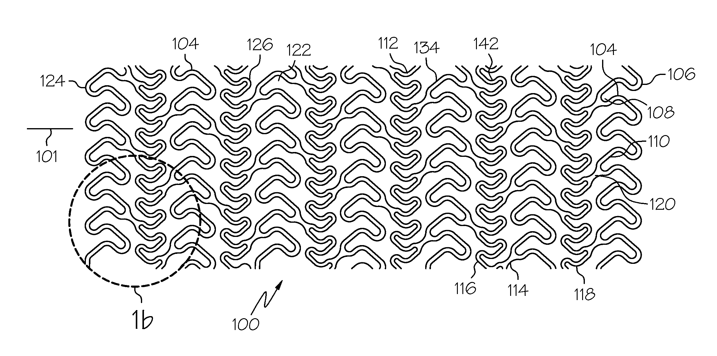
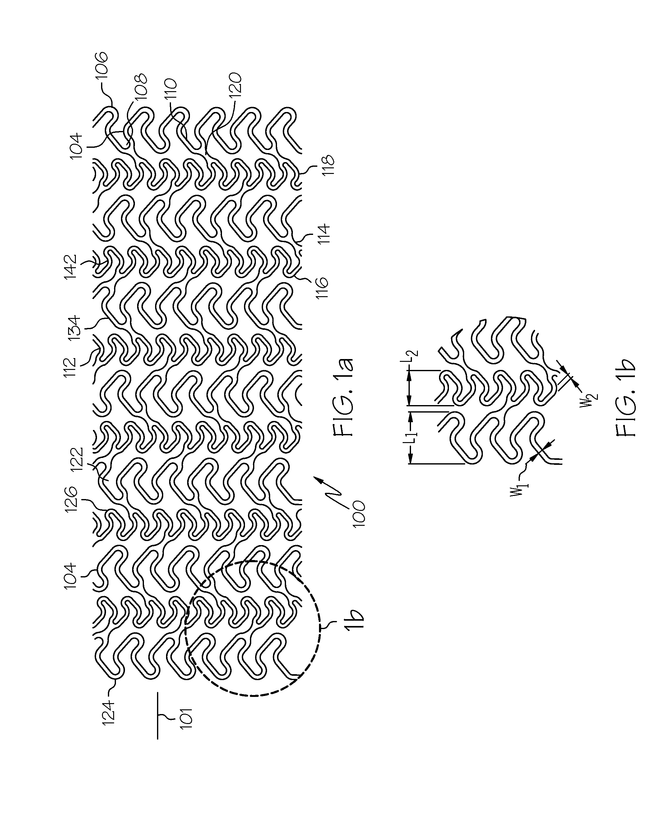
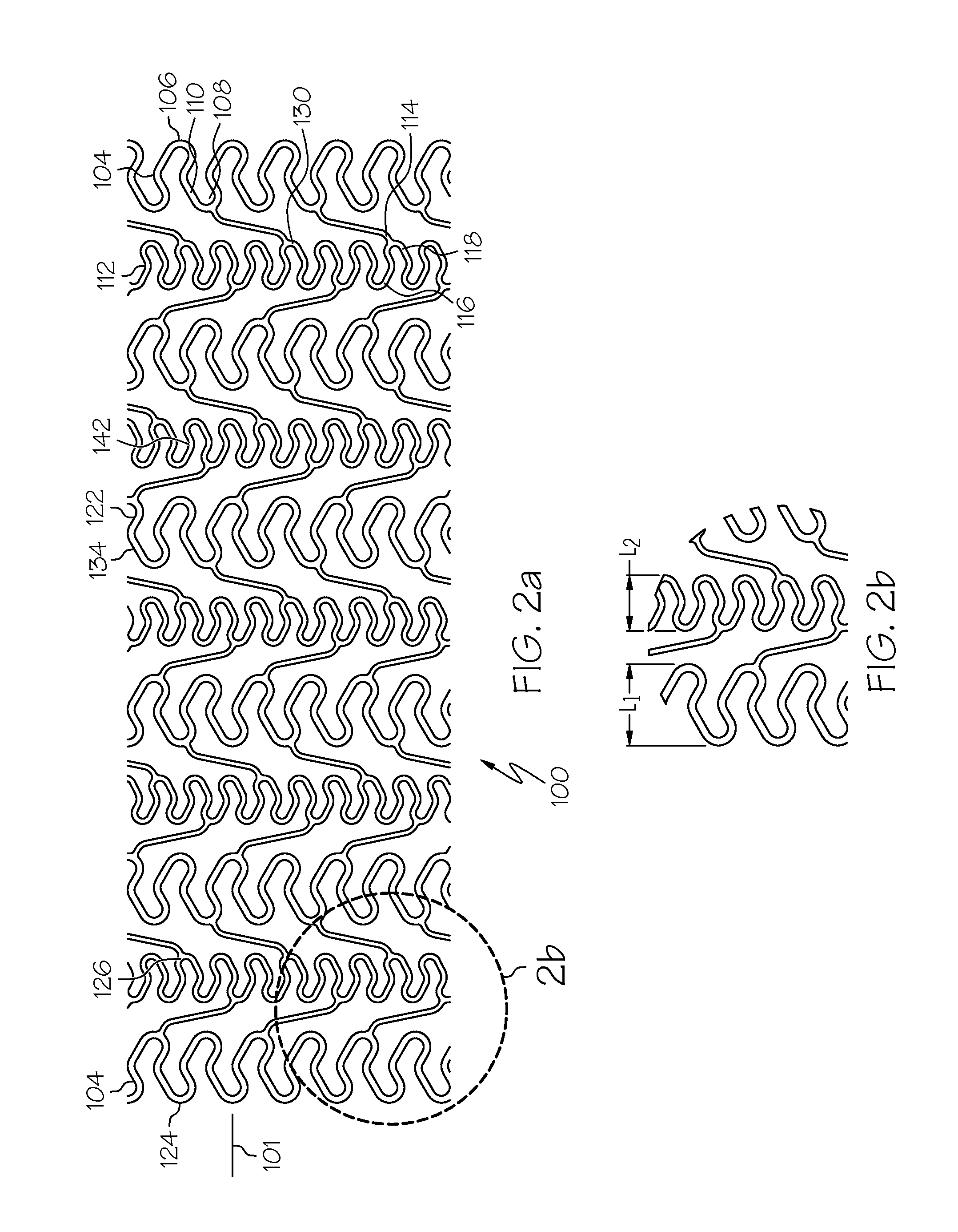
The invention is a stent with alternating bands of peaks and troughs that create a pathway around the stent. The peaks and troughs are oriented at an angle with respect to the longitudinal axis of the stent. The stent can have different numbers of peaks and troughs in each band, and the bands can be connected by straight or curved connectors. The stent can be designed to have a longitudinally adjacent band with different numbers of peaks and troughs, or the bands can be designed to have the same number of peaks and troughs. The stent can also have different widths for the peaks and troughs in each band. The technical effects of the invention include improved flexibility, reduced likelihood of blockages, and improved blood flow.

Problems solved by technology

Increased flexibility in a stent, however, typically comes at the expense of scaffolding strength.
Moreover, design features which may result in increased flexibility may also result in protruding edges which may damage vessels walls or catheter balloons during delivery of the stent through tortuous vasculature.
Stents where all of the openings are parallel to one another, however, may experience excessive torque upon delivery through tortuous vessels and resultant deployment problems.

Method used


Image

  • Stent
  • Stent
  • Stent

Examples


Embodiment Construction

[0065]While this invention may be embodied in many different forms, there are described in detail herein specific embodiments of the invention. This description is an exemplification of the principles of the invention and is not intended to limit the invention to the particular embodiments illustrated.

[0066]For the purposes of this disclosure, like reference numerals in the figures shall refer to like features unless otherwise indicated.

[0067]Also for the purposes of this disclosure, the term ‘bent strut’ does not implicate a method of manufacture and is intended to include struts which have curves, struts which are angled, and struts which are curvilinear, regardless of how the struts or the stent as a whole are manufactured. Bent struts as referred to herein typically have two segments joined by a bent portion.

[0068]Finally, for the purposes of this disclosure, the expression ‘total circumferential length’ refers to the length of a circumferential band as the band is traversed abo...


PUM


Abstract

A stent comprises a plurality of circumferential bands. Circumferential bands which are adjacent one another are connected one to the other. The circumferential bands include peaks and troughs interconnected by bent struts. The bands may overlap or may be connected by connectors.

Description

CROSS REFERENCE TO RELATED APPLICATIONS[0001]This Application a continuation-in-part application of U.S. application Ser. No. 10 / 042,634, filed Jan. 9, 2002, which is a continuation-in-part application, claiming priority from U.S. application Ser. No. 09 / 957,983 filed Sep. 21, 2001 which claims the benefit of U.S. provisional applications No. 60 / 234,548, filed Sep. 22, 2000, No. 60 / 272,651 filed Mar. 1, 2001 and No. 60 / 272,906 filed Mar. 1, 2001, all of which are incorporated herein in their entirety by reference.BACKGROUND OF INVENTION[0002]The use of stents in bodily lumen is well known. A stent is typically delivered in an unexpanded state to a desired location in a bodily lumen and then expanded. The stent may be expanded via the use of mechanical device such as a balloon or the stent may be self-expanding.[0003]Because a stent often must be delivered through tortuous anatomy, it is desirable for the stent to be flexible. Increased flexibility in a stent, however, typically come...

Claims


Application Information

Patent Timeline
Patent Type & Authority Applications(United States)
IPC IPC(8): A61F2/82A61F2/84A61F2/90
CPCA61F2/91A61F2/915A61F2002/91508A61F2002/91516A61F2002/91575A61F2002/91533A61F2002/91558A61F2002/91566A61F2002/91525A61F2/06A61F2/04
Inventor GREGORICH, DANIELGIRTON, TIMOTHY S.
Owner BOSTON SCI SCIMED INC
Learn More