Deicing nose of an axial turbine engine compressor

a compressor and axial turbine technology, applied in the field of turbines, can solve the problems of obstructing the inlet to the primary flow path, limiting the efficiency of the de-icing system, and unable to reach the upper surface directly by the air j

Active Publication Date: 2019-09-17
SAFRAN AERO BOOSTERS SA
View PDF2 Cites 3 Cited by
  • Summary
  • Abstract
  • Description
  • Claims
  • Application Information

AI Technical Summary

Benefits of technology

[0039]The invention enables a de-icing flow to be injected along the leading edge of the vane being treated. This makes it possible to cover more of the radial height of the vane, and in particular to work from one extremity of the vane. Additionally, the orientation of the flow makes it possible to treat the lower surface of the vane as well as the upper surface as the injected fluid is distributed by the leading edge.

Problems solved by technology

These same operating conditions may cause icing, i.e. ice may form inside the turbo-jet engine.
In extreme cases, the accumulation of ice can block the spaces between neighbouring vanes, thereby entirely obstructing the inlet to the primary flow path.
However, the efficiency of this de-icing system is limited because an ice deposit can nonetheless form on the vane about the impact zone.
In particular, when the incline of the chord of the vane is too great, the upper surface cannot be reached directly by the air jet.

Method used


Image

  • Deicing nose of an axial turbine engine compressor
  • Deicing nose of an axial turbine engine compressor
  • Deicing nose of an axial turbine engine compressor

Examples


Embodiment Construction

[0043]In the description below, the terms inner and outer refer to a position in relation to the axis of rotation of an axial turbine engine. The axial direction corresponds to the direction along the axis of rotation of the turbine engine. The radial direction is perpendicular to the axis of rotation. Upstream and downstream refer to the main direction of flow of the flow in the turbine engine.

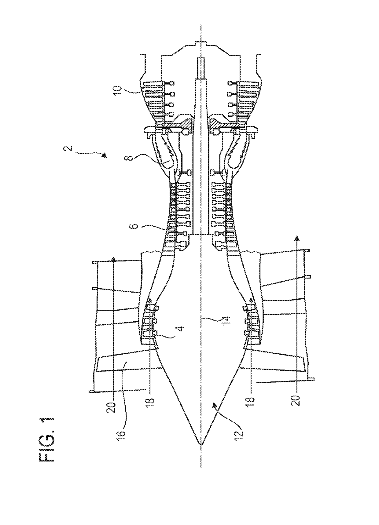
[0044]FIG. 1 is a simplified representation of an axial turbine engine. In this specific case, it is a dual-flow turbo-jet engine. The turbo-jet engine 2 has a first compression level, referred to as the low-pressure compressor 4, a second compression level, referred to as the high-pressure compressor 6, a combustion chamber 8, and one or more turbine levels 10. When in operation, the mechanical power of the turbine 10 transmitted via the central shaft to the rotor 12 moves the two compressors 4 and 6. These latter have several rows of rotor blades associated with rows of stator vanes. The ro...


PUM


Abstract

The invention relates to a de-icing splitter nose (22) of an axial turbine engine, notably a de-icing splitter nose of a turbo-jet engine compressor. The splitter nose includes an annular row of vanes (26), each of which has a radially extending leading edge (36), and a de-icing system (28) based on hot-air injection. The injection is pulsed, i.e. discontinuous. The system (28) includes an annular row of injection orifices for injecting de-icing fluid (44) onto the vanes (26) in respective injection directions (46). Each injection orifice is associated with a vane such that the injection directions thereof are substantially parallel to the leading edge (36) of the related vane, enabling said vane (26) to be de-iced.

Description

TECHNICAL DOMAIN[0001]The invention relates to the de-icing of a splitter nose of an axial turbine engine. More specifically, the invention relates to a splitter nose with hot-gas de-icing for an axial turbine engine. The invention also relates to an axial turbine engine, in particular a turbo-jet engine of an aeroplane or a turboprop of an aircraft.PRIOR ART[0002]A turbo-jet engine typically has an inlet split into a primary flow path and a secondary flow path such as to duct the primary flow and the secondary flow respectively. This annular separation is achieved using a splitter nose that splits the incoming flow according to predetermined proportions in order to guarantee a given performance and a given thrust, as a function of operating conditions.[0003]These same operating conditions may cause icing, i.e. ice may form inside the turbo-jet engine. In particular, a layer of ice may cover the splitter nose itself, extending as far as the vanes of the stator housed in the splitter...

Claims


Application Information

Patent Timeline
Patent Type & Authority Patents(United States)
IPC IPC(8): F02C7/04F01D25/02F02C7/047F02K3/02F02K3/06F04D29/32
CPCF01D25/02F02K3/02F02C7/047F05D2250/313F05D2220/323F05D2240/12F05D2260/20F04D29/321F02K3/06F04D29/584Y02T50/60
Inventor DE VRIENDT, OLIVIERSCHUSTER, LAURENT
Owner SAFRAN AERO BOOSTERS SA
Why Eureka
Try Eureka