
Orthotic shoe and insole assemblies

a technology of orthotic shoes and insoles, applied in the direction of insoles, footwear, apparel, etc., can solve the problems of limited expansion of orthotic shoes, limited cushioning and comfort potential of orthotic shoes, and shoes that inadequately attenuate shock and impact over a large surface area of the user's foot, so as to improve biomechanical function, increase shock attenuation, and enhance comfort

Inactive Publication Date: 2012-01-26
TEMPLE UNIVERSITY
View PDF0 Cites 16 Cited by
  • Summary
  • Abstract
  • Description
  • Claims
  • Application Information

AI Technical Summary

Benefits of technology

[0005]Aspects of the invention relate to an orthotic shoe sole assembly and an orthotic insole that provide a unique form of central axis torsional support and a pressure absorbing energy return system in the sole that work in conjunction to provide for enhanced comfort, improved biomechanical function, and increased shock attenuation during the contact and propulsive phases of gait.
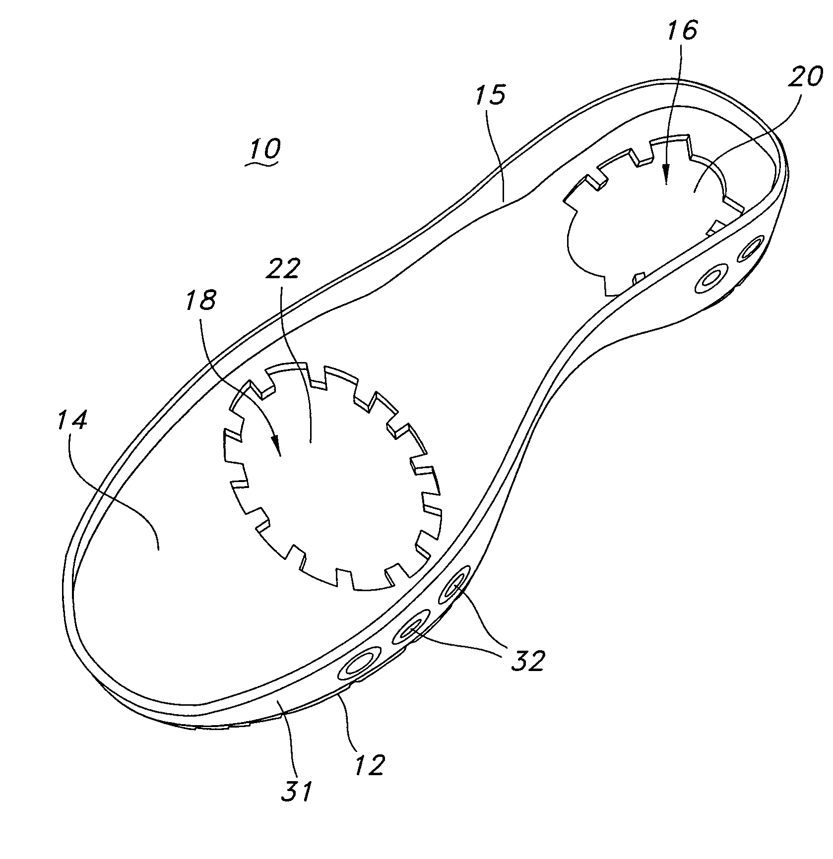
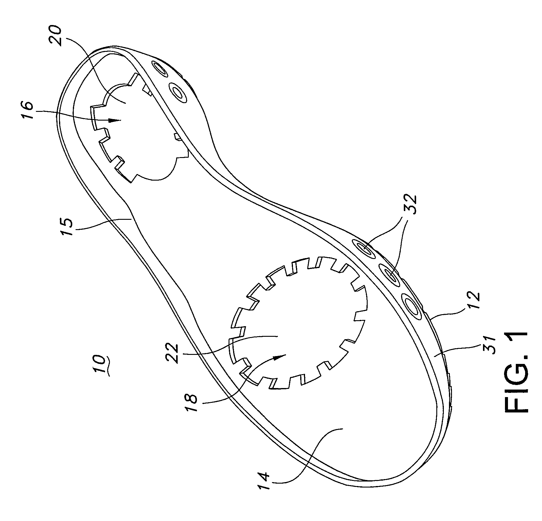
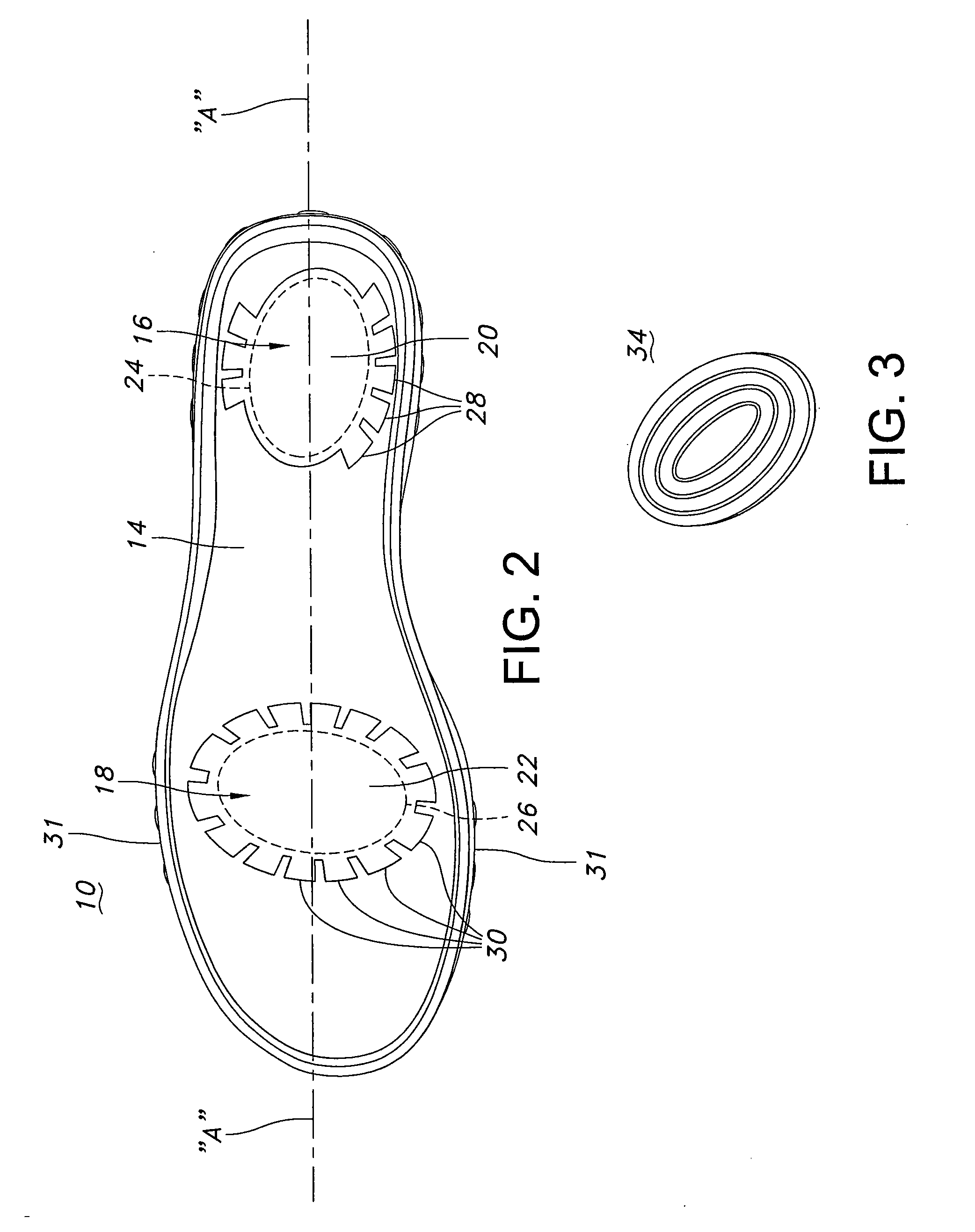
[0006]The orthotic shoe sole assembly disclosed herein includes a shoe sole defining a cavity and a resilient member positioned within the cavity. The cavity includes a series of channels into which the resilient member may expand under the force of compression. Accommodating expansion of a resilient member is beneficial for enhancing the distribution of forces applied by the foot thereby resulting in more efficient energy return of those forces.

Problems solved by technology

While many known orthotic shoes and insoles incorporate shock-attenuating materials for alleviating one or more of the above conditions, such shoes and insoles typically limit expansion of the shock-attenuating materials.
Expansion of the shock-attenuating material is limited by the interior confines of those shoes thereby limiting the cushioning and comforting potential of the shock-attenuating materials.
For that reason, those shoes inadequately attenuate shock and impact over a large surface area of the user's foot.
Furthermore, those orthotic shoes and insoles do not typically support an end-user's foot along its central axis.

Method used


Image

  • Orthotic shoe and insole assemblies
  • Orthotic shoe and insole assemblies
  • Orthotic shoe and insole assemblies

Examples


Embodiment Construction

[0018]The invention will next be illustrated with reference to the figures. Such figures are intended to be illustrative rather than limiting and are included herewith to facilitate explanation of the present invention. In the figures, like items numbers refer to like elements throughout.

[0019]FIGS. 1 and 2 depict a top side perspective view and a top plan view, respectively, of shoe sole 10 according to one exemplary embodiment of the invention. Shoe sole 10 is a component of a shoe, such as a sport shoe, a dress shoe, a therapeutic shoe or slipper, for example. Shoe sole 10 may also be referred to in the art as an outsole. According to this exemplary embodiment, shoe sole 10 is a double-rocker sole, as described in greater detail with references to FIG. 8. Shoe sole 10 defines tread surface 12, a small portion of which is illustrated, for contacting a ground surface (not shown). Sole 10 further defines an exposed surface 14 (i.e., exposed to an end-user) that is oriented opposite ...


PUM


Abstract

An orthotic shoe sole assembly and an orthotic insole are disclosed herein. The orthotic shoe assembly includes a shoe sole having an exposed surface and at least one exposed cavity accessible via the exposed surface. The at least one exposed cavity includes a central region and a plurality of channels extending from the central region. A resilient member is removably positioned within the central region of the exposed cavity. The resilient member is configured to resiliently expand into at least one of the plurality of channels of the exposed cavity. The orthotic insole is removably positioned to selectively conceal the exposed cavity of the shoe sole and the resilient member. The orthotic insole includes a central axis member for supporting a foot along its central axis.

Description

FIELD OF THE INVENTION[0001]The present invention relates to orthotic shoe and insole assemblies.BACKGROUND OF THE INVENTION[0002]External orthotic treatment of the human foot is desirable to enhance comfort of the foot, relieve pain associated with weakness, injuries, and malformation of the foot and to prevent tissue damage from conditions such as plantarfasciitis, heel pain, arch strain, ball-of-the-foot pain (metatarsalgia), tendonitis, arthritis and diabetic foot disorders.[0003]While many known orthotic shoes and insoles incorporate shock-attenuating materials for alleviating one or more of the above conditions, such shoes and insoles typically limit expansion of the shock-attenuating materials. Expansion of the shock-attenuating material is limited by the interior confines of those shoes thereby limiting the cushioning and comforting potential of the shock-attenuating materials. For that reason, those shoes inadequately attenuate shock and impact over a large surface area of ...

Claims


Application Information

Patent Timeline
IPC IPC(8): A43B13/14
CPCA43B3/0031A43B7/144A43B7/1445A43B17/02A43B13/187A43B13/20A43B7/1465A43B7/1464
Inventor WHITNEY, KENDRICKMCGUIRE, JAMESPOSOFF, RICHARD
Owner TEMPLE UNIVERSITY
Learn More