Valve timing control device of internal combustion engine

a timing control and internal combustion engine technology, applied in the direction of valve arrangements, combustion engines, machines/engines, etc., can solve the problems that the torque load and vibration of the engine cannot be reduced to a satisfied level

Inactive Publication Date: 2012-01-26
HITACHI AUTOMOTIVE SYST LTD
View PDF5 Cites 14 Cited by
  • Summary
  • Abstract
  • Description
  • Claims
  • Application Information

AI Technical Summary

Benefits of technology

[0009]That is, in accordance with the present invention, there is provided a valve timing control device of an internal combustion engine, which can vary the compression ratio of the engine in accordance with an engine environment at the engine starting.
[0010]In accordance with a first aspect of the present invention, there is provided a valve timing control device of an internal combustion engine, which comprises a drive rotation member driven by a crankshaft of the engine; a driven rotation member fixed to a camshaft that actuates engine valves to open and close, the drive rotation member and driven rotation member being coaxially arranged to make a relative rotation therebetween; a phase varyi...

Problems solved by technology

This brings about such an undesired state that even in a condition wherein the engine can start with a smaller compression ratio, the engine ...

Method used


Image

  • Valve timing control device of internal combustion engine
  • Valve timing control device of internal combustion engine
  • Valve timing control device of internal combustion engine

Examples


first embodiment

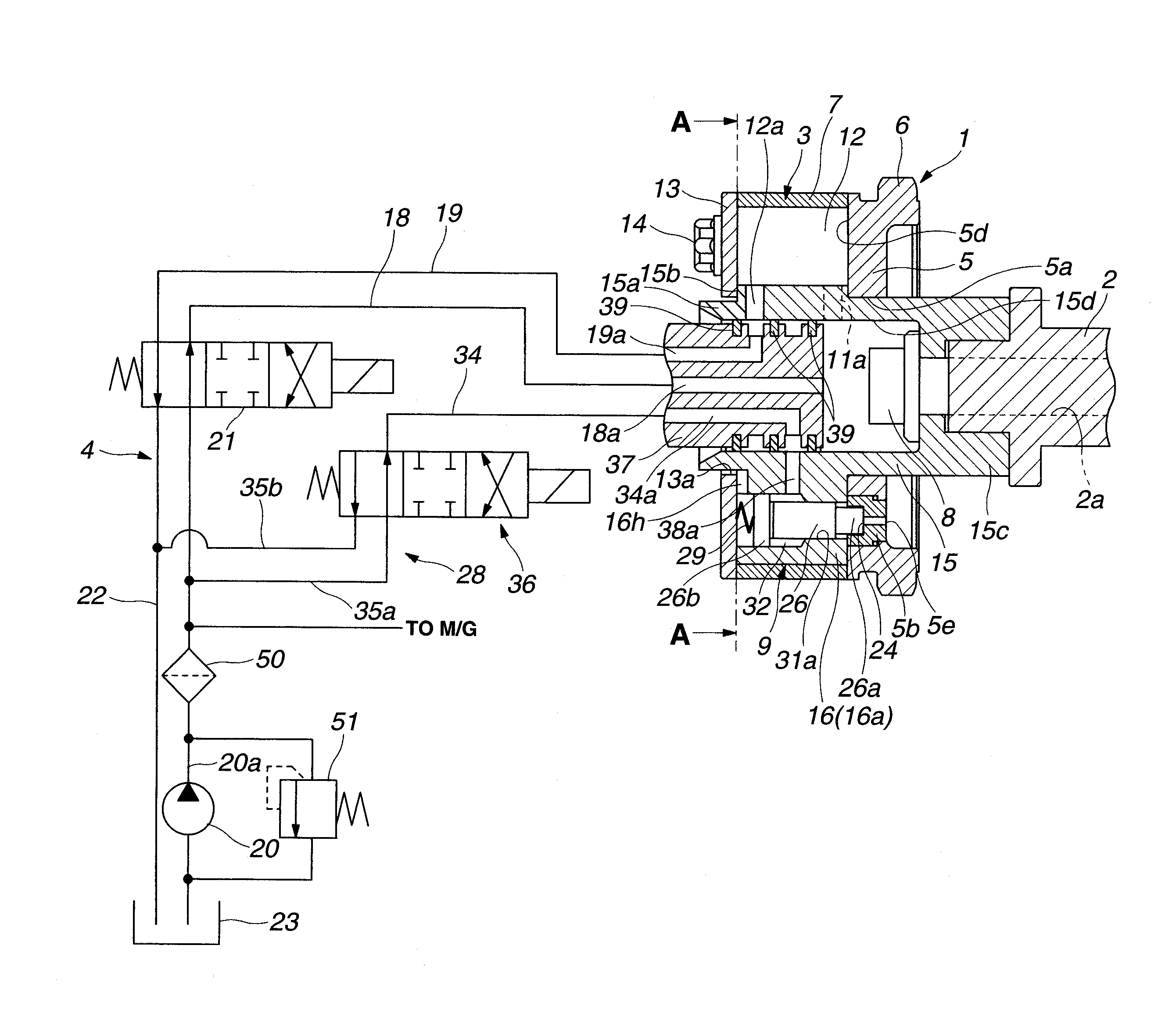
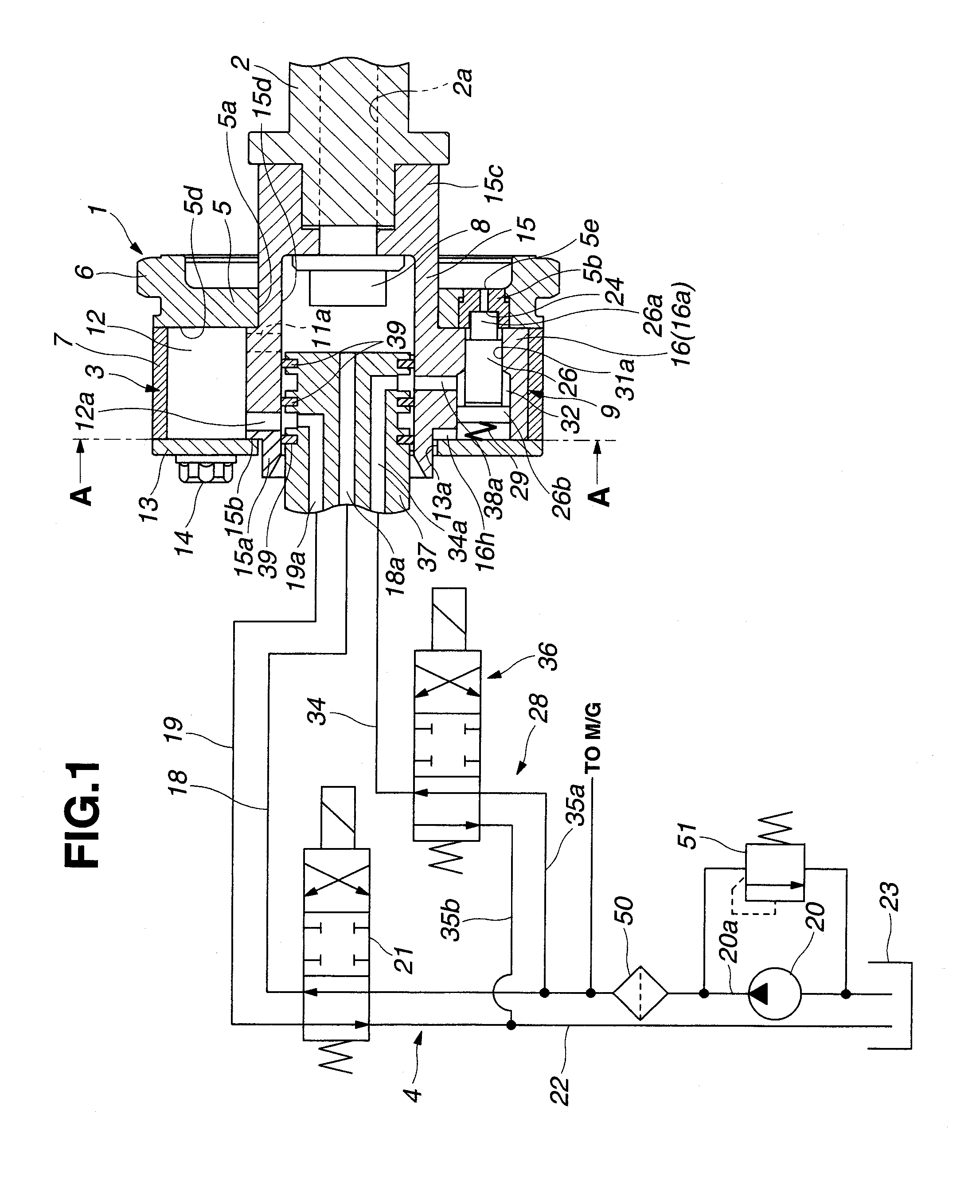
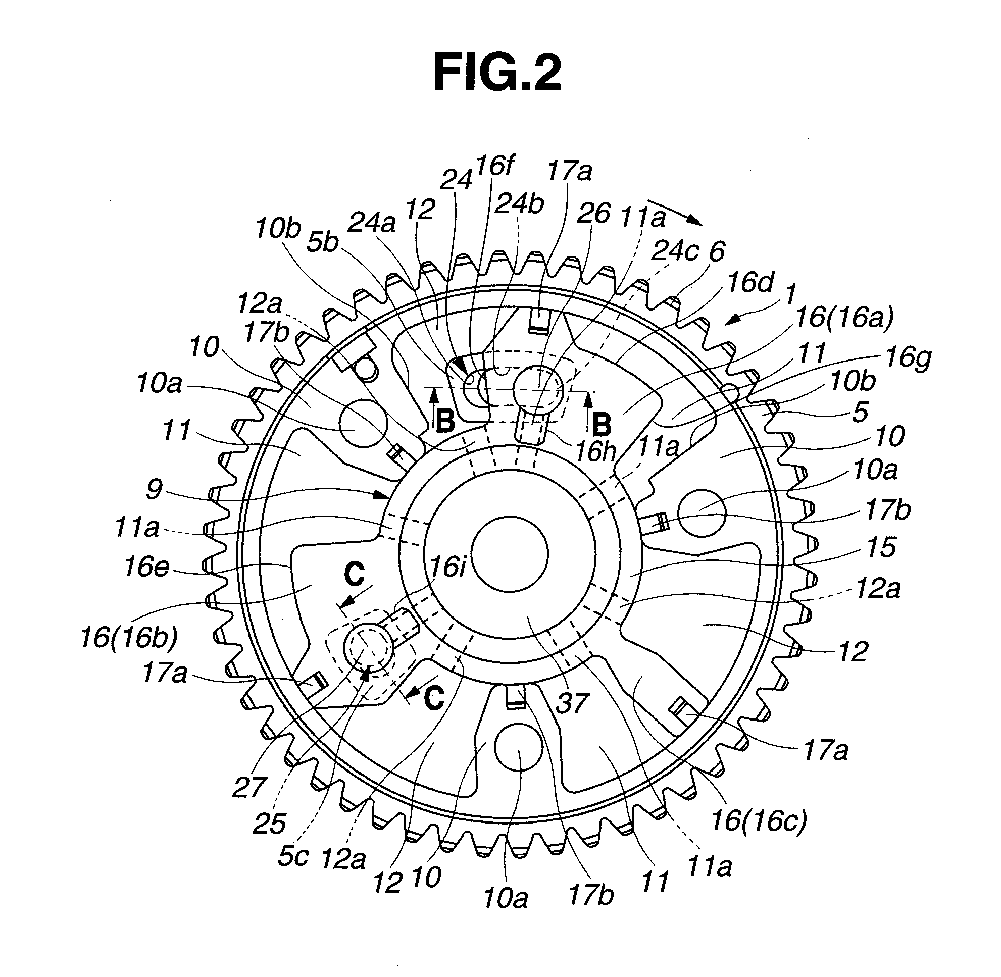
[0041]Referring to FIGS. 1 and 2, there is shown a first embodiment of a valve timing control device of the present invention.

[0042]As is seen from FIG. 1, the valve timing control device comprises a rotatable sprocket 1 that is driven by a crankshaft (not shown) of an associated engine through a timing chain (not shown), an intake camshaft 2 that is arranged to extend in an axial direction of the engine and rotatable relative to rotatable sprocket 1, a phase varying mechanism 3 that is arranged between sprocket 1 and intake camshaft 2 to vary a relative angle (or relative phase) defined therebetween, and a first hydraulic circuit 4 that operates phase varying mechanism 3 in a given way.

[0043]The sprocket 1 comprises a discal sprocket body 5 and an annular gear portion 6 that is integrally formed around discal sprocket body 5 and meshed with the above-mentioned timing chain. The discal sprocket body 5 constitutes a rear cover for covering a rear opening of an after-mentioned housing...

second embodiment

[0109]Referring to FIG. 12, there is shown a second embodiment of a valve timing control device of the present invention.

[0110]In this second embodiment, a third electromagnetic switch valve 40 is further employed. That is, as shown in the drawing, third electromagnetic switch valve 40 is arranged between first electromagnetic switch valve 21 and each of retarding and advancing fluid passages 18 and 19.

[0111]The third electromagnetic switch valve 40 is of an ON / OFF type having two positions.

[0112]As shown, third electromagnetic switch valve 40 comprises a valve body 41 having two passages 41b and 41a that are connected to retarding and advancing fluid passages 18 and 19 respectively.

[0113]Within valve body 41, there is axially movably disposed a spool member 42 that has two lands 42a and 42b to open and close passages 41a and 41b respectively. For actuating spool member 42 with the aid of the electronic controller (not shown), there is provided an electric solenoid 43. That is, upon...

third embodiment

[0118]Referring to FIG. 13, there is shown a third embodiment of a valve timing control device of the present invention.

[0119]In this third embodiment, in place of third electromagnetic switch valve 40 employed in the second embodiment, a mechanical switch valve 45 is used that practically uses a pilot pressure.

[0120]That is, the switch valve 45 is of ON / OFF type having two positions.

[0121]As shown, the switch valve 45 comprises a valve body 46 having two passages 46b and 46a that are connected to retarding and advancing fluid passages 18 and 19 respectively.

[0122]Within valve body 46, there is axially movably disposed a spool member 47 that has two lands 47a and 47b to open and close passages 46a and 46b respectively.

[0123]As shown, a left end of spool member 47 is exposed to a pressure chamber 49 that is connected to discharge passage 20a through a pilot passage 48, and a biasing spring 50 is connected to a right end of spool member 47 to bias spool member 47 leftward in the draw...


PUM


Abstract

A valve timing control device comprises a drive rotation member driven by a crankshaft of an internal combustion engine; a driven rotation member fixed to a camshaft that actuates engine valves to open and close, the drive rotation member and driven rotation member being coaxially arranged to make a relative rotation therebetween; a phase varying mechanism that rotates the driven rotation member relative to the drive rotation member within a given angle, the phase varying mechanism being able to cause the driven rotation member to take the most-retarded phase position, the most-advanced phase position and a middle phase position defined between the most-retarded phase position and the most-advanced phase position; and a position keeping mechanism that is able to keep the driven rotation member at least the most-retarded phase position and the middle phase position at the time of starting the engine, and is able to select one of the most-retarded phase position and the middle phase position in accordance with an operation condition of the engine.

Description

BACKGROUND OF THE INVENTION[0001]1. Field of the Invention[0002]The present invention relates to a valve timing control device of an internal combustion engine, which controls open / close timing of engine valves, such as intake and exhaust valves of the engine, in accordance with an operation condition of an associated motor vehicle.[0003]2. Description of the Related Art[0004]As is known in the art, Atkinson Cycle in internal combustion engines is of a cycle type that improves a thermal efficiency of the engine by increasing compression ratio under operation of the engine. For realization of the Atkinson Cycle, a valve timing control device is usually employed, by which a close timing (viz., IVC) of each intake valve is retarded relative to the bottom dead center (viz., BDC) of the piston thereby to increase a volumetric efficiency of each cylinder. In this case, it is necessary for the valve timing control device to much increase a valve operation angle (viz., an angle for which th...

Claims


Application Information

Patent Timeline
IPC IPC(8): F01L1/344
CPCF01L1/3442F01L2001/3443F01L2001/34433F01L2001/34453Y02T10/18F01L2001/34469F02D13/0219F02D2013/0292F01L2001/34459Y02T10/12
Inventor KATO, HIROYUKITSURUTA, SEIJIWATANABE, KOTAROICHINOSAWA, YOSHINORI
Owner HITACHI AUTOMOTIVE SYST LTD
Why Eureka
Try Eureka