Increase torque output from reciprocating piston engine

a reciprocating piston and engine technology, applied in the direction of connecting rods, bearings, shafts and bearings, etc., can solve the problems of lowering the engine torque output, increasing friction losses, and reducing the torque output of the engine, so as to reduce the amount of exhaust pollution and increase the clearance tolerance

Inactive Publication Date: 2012-01-26
SWIENINK HENDRIKUS JOHAN
View PDF1 Cites 0 Cited by
  • Summary
  • Abstract
  • Description
  • Claims
  • Application Information

AI Technical Summary

Problems solved by technology

This revealed that the full pressure created by the detonation of the fuel above the piston is not in synchronous with maximum crankshaft torque output position and therefore lower the effectiveness of the engine torque output
This created a side force to the piston, pushing the piston rings against the cylinder wall, increase friction losses.
This compromise over time the sealing function of the piston rings due to wear and reducing compression as clearance increase between piston rings and cylinder wall, lowering the engine torque output.

Method used


Image

  • Increase torque output from reciprocating piston engine
  • Increase torque output from reciprocating piston engine
  • Increase torque output from reciprocating piston engine

Examples


Embodiment Construction

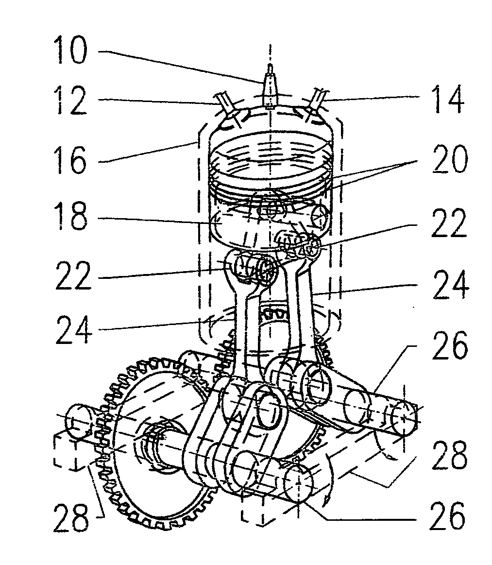
FIG. 6, FIG. 7a, FIG. 8a and FIG. 13. The Embodiment

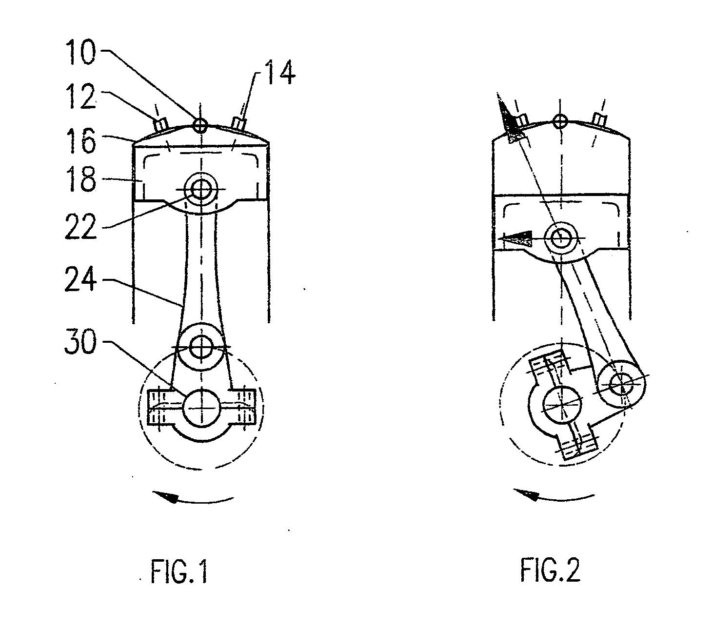
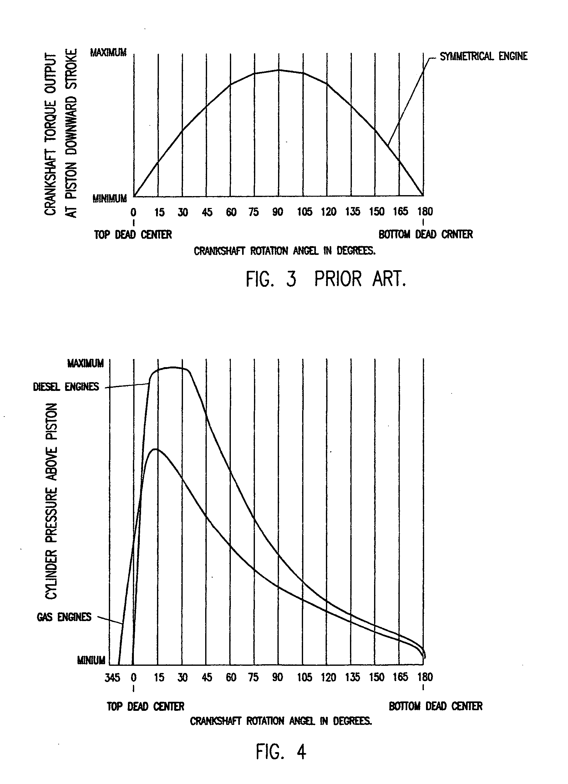
[0040]By moving the crankshaft center in a offset location from cylinder and piston centerline, the maximum crankshaft leverage position has moved closer to detonation timing and piston “top dead center”. The torque curve of an offset crankshaft in that position is shown at FIG. 6.

[0041]Also shown here is the curve from a symmetrical layout engine (prior art) to compare the difference positions of maximum torque output between the two type engines in relation to the crankshaft angle of rotation.

[0042]At a symmetrical engine (prior art) each of the piston up and down strokes are 180 degrees of the crankshaft rotation. Due to the offset used in this embodiment, the downward cycle time has increased and the upwards cycle time decreased by the same amount, total to 360 degrees of one rotation of the crankshaft. This different amount is depending on the piston stroke, the offset location and length of connecting rod and the crankshaft d...


PUM


Abstract

Reciprocating powered driven engine having a piston with multiplier connecting rods, driving multiplier crankshafts. Maximum crankshaft torque output positioned closer to the detonation timing and piston “top dead center” when cylinder above piston volume is at a lower value. Reduced engine friction losses by canceling piston side forces with the use of multiplier crankshafts positioned in offset and mirror image from piston and cylinder center line.

Description

FEDERALLY SPONSORED RESEARCH [0001]Not applicableSEQUENCE LISTING OR PROGRAM [0002]Not applicableBACKGROUND FIELD[0003]This application relates to increase torque output from reciprocating driven piston engine.BACKGROUNDPrior Art[0004]Most present in use (prior art) reciprocating driven piston type engines are of a symmetrical layout.[0005]At a symmetrical engine {prior art) the cylinder and piston center line passes through the crankshaft pivot center of rotation see FIG. 1[0006]The torque output of a this type engine layout is minimum at piston top position when connecting rod from piston to crankshaft is in line with cylinder center. This position is called “top dead center” and the crankshaft position is called at “zero” degrees.[0007]The cylinder volume above piston is minimum at the start of the power stroke and gasses are maximum compressed. As detonation of the gasses follows and the pressure increased, the piston is driven downwards, rotating the crankshaft over 180 degrees...

Claims


Application Information

Patent Timeline
Patent Type & Authority Applications(United States)
IPC IPC(8): F02B75/32F16C3/04
CPCY10T74/2173F02B75/065
Inventor SWIENINK, HENDRIKUS JOHAN
Owner SWIENINK HENDRIKUS JOHAN
Why Eureka
Try Eureka