Controller of Contact Sensing Type Using Optical Principle for Controlling a Pointer on a Display Screen

a technology of contact sensing and control pointer, which is applied in the direction of instruments, computing, electric digital data processing, etc., can solve the problems of weakening the sensitivity of the motion transducer, the controller of u.s. patent no. 6,621,483 is not suitable for use in slim and portable electronic devices, and the inability to have a thin control device, etc., to achieve enhanced sensitivity of the present invention of the controller, and the effect of thin heigh

Inactive Publication Date: 2012-01-26
LAI PO SHENG
View PDF6 Cites 3 Cited by
  • Summary
  • Abstract
  • Description
  • Claims
  • Application Information

AI Technical Summary

Benefits of technology

[0004]The present invention of the controller of contact sensing type using optical principle for controlling a pointer on a display screen. The controller having the optical element with a length vertically much shorter than conventional optical element and prior art, thus having the advantage of a thinner height and more suitable for using in slim and portable electronic products.
[0005]The present invention has a primary objective to provide the controller of contact sensing type using optical principle for controlling a poin

Problems solved by technology

On account of this, the optical element having a certain vertical height for focusing and dispersing light. FIG. 1 of U.S. Pat. No. 6,621,483 indicates that the vertical height of the optical element is approximately a few times of the thickness of the portion of the tip of a human digit, thus make it impossible to have a thin controlling device.
In

Method used


Image

  • Controller of Contact Sensing Type Using Optical Principle for Controlling a Pointer on a Display Screen
  • Controller of Contact Sensing Type Using Optical Principle for Controlling a Pointer on a Display Screen
  • Controller of Contact Sensing Type Using Optical Principle for Controlling a Pointer on a Display Screen

Examples


Embodiment Construction

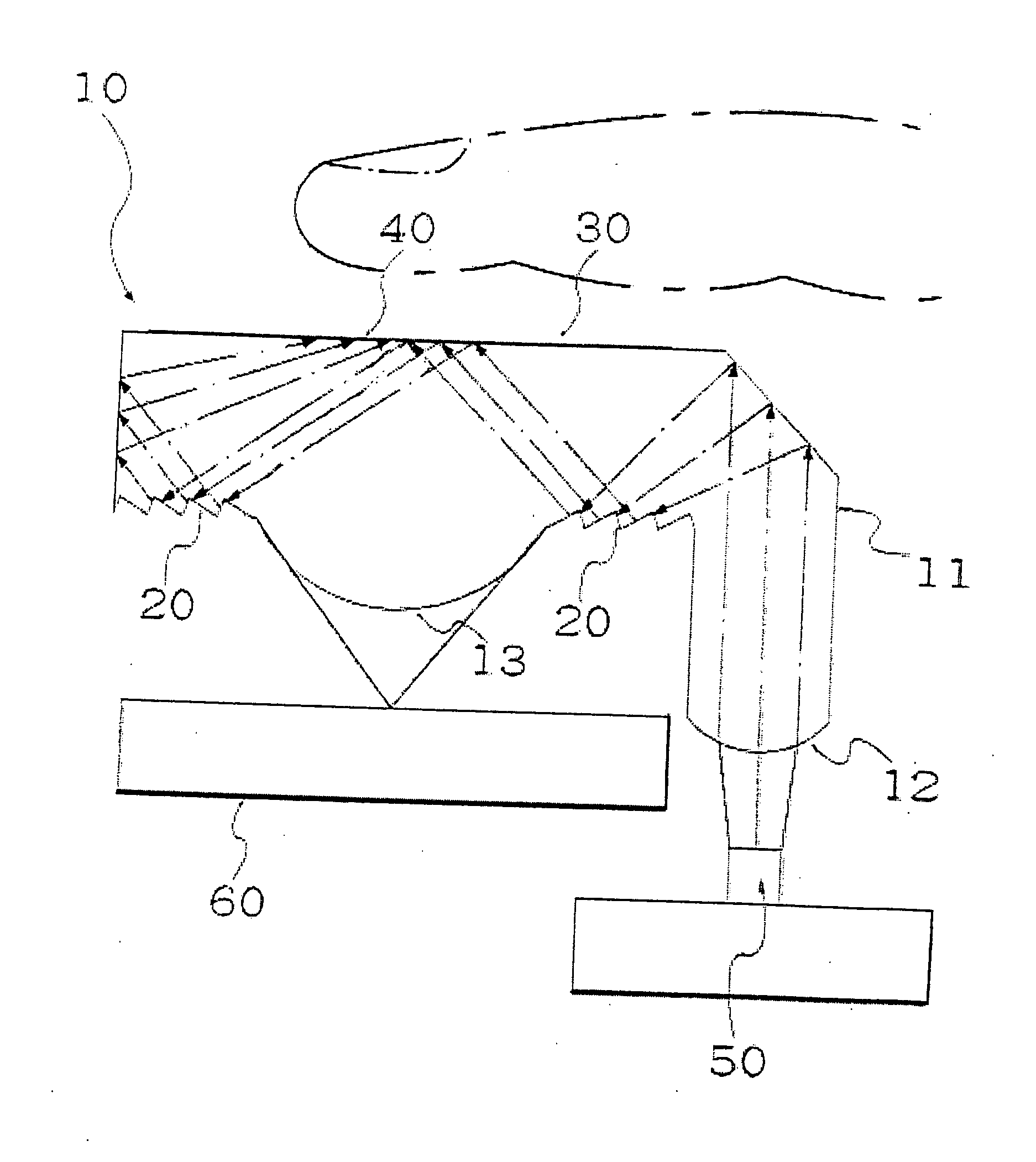
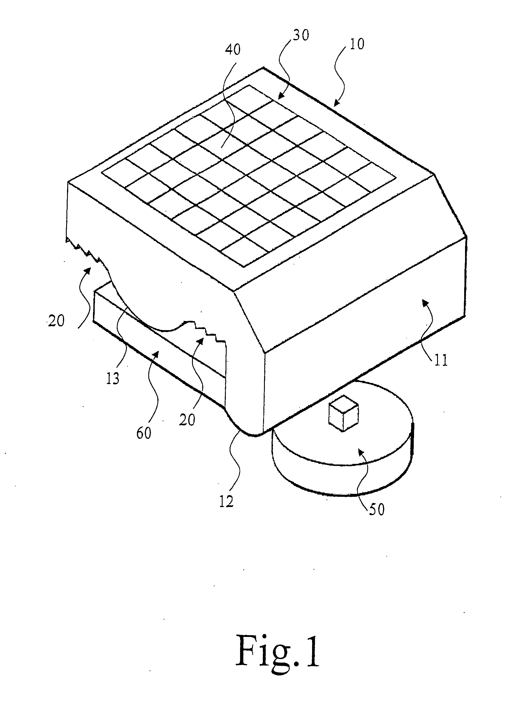
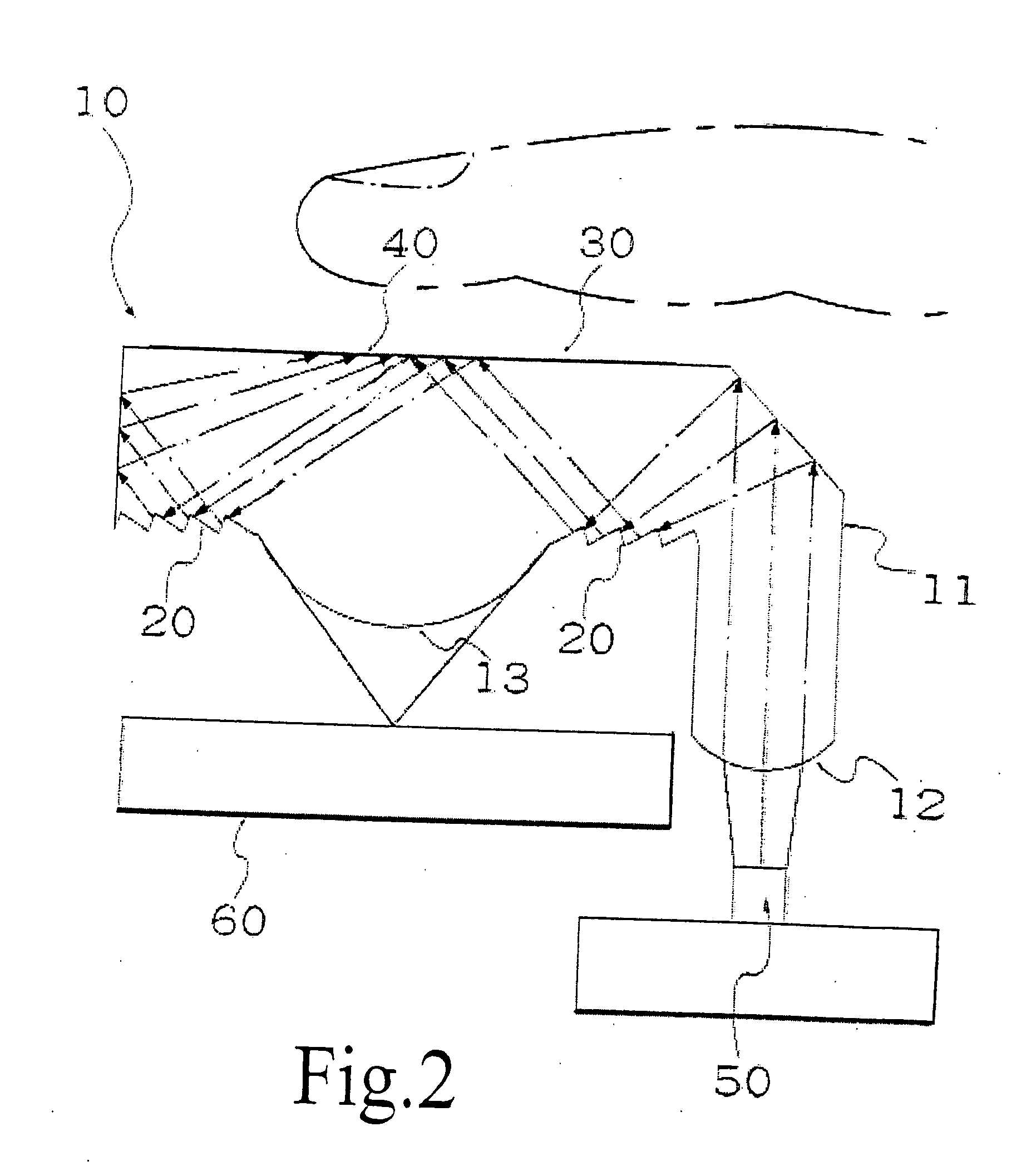
[0020]The present invention of a controller of contact sensing type using optical principle for controlling a pointer on a display screen, with reference from FIGS. 1 to 4, includes an optical element 10, an inbound light source 50 and a motion transducer 60. The inbound light source 50 and the motion transducer 60 are of prior art, thus their related principles and structures will not be described in this invention.

[0021]The optical element 10 is a lens having the characteristics of total internal reflection. The optical element 10 has a light source area 11, an intensified structure 20 for intensifying the refraction and reflection effects, a contact surface 30 for placing a portion of the tip of a human digit, an array of micro structure 40 for enhancing the brightness of the reflected light of the contact surface 30.

[0022]The light source area 11 can be disposed on top, underneath or on either side of the optical element 10. The light source area 11 having a surface for directin...


PUM


Abstract

The present invention of a controller of contact inductive type using optical principle for controlling a pointer on a display screen includes an optical element, an inbound light source for illuminating the optical element, and a motion transducer for receiving the reflected light from the optical element. The optical element is a lens component having the characteristics of total internal reflection. The optical element having a light source area, the inbound light source enters the optical element through the light source area. An Intensified structure is located on the bottom of the optical element for intensifying the refraction and reflection percentages of the light inside the optical element, in order to utilize the light at a higher ratio. The inbound light source is finally reflected to a contact surface on top of the optical element for placing the portion of the tip of a human digit. An array of micro structure is located on the contact surface for intensifying the brightness of the reflected light from where the portion of the tip of the human digit is placed, the light is then directed to the motion transducer through a surface on the bottom of the optical element.

Description

BACKGROUND OF THE INVENTION[0001]The present invention relates to an apparatus for controlling a position of a screen pointer for an electronic device having a display screen and more particularly to a controller of contact sensing type using optical principle. U.S. Pat. No. 6,621,483 employs a contact type sensing device for controlling a position of a screen pointer for an electronic device using optical theory. The said sensing device of U.S. Pat. No. 6,621,483 having an optical element, the optical element comprising an imaging surface against which a portion of the tip of a human digit may be placed; a light source for illuminating that portion of the tip of the digit that is placed against the imaging surface, thereby generating reflected images; a lens for receiving the reflected images from the bottom part of the optical element and directing the reflected images onto a motion transducer; the motion transducer generating digital representations of the reflected images and di...

Claims


Application Information

Patent Timeline
IPC IPC(8): G06F3/042
CPCG06F3/03547G06F2203/04109G06F2203/0338G06F3/042
Inventor LAI, PO-SHENG
Owner LAI PO SHENG
Why Eureka
Try Eureka