Image sensor for generating stereoscopic images

a stereoscopic image and image sensor technology, applied in the direction of electrical equipment, semiconductor devices, television systems, etc., can solve the problems of deteriorating stereo effect, inability to solve following limitations, and inability to capture direction (z), so as to facilitate mechanical alignment of two image sensors and enhance stereo effect , the effect of low stereo camera pri

Inactive Publication Date: 2012-01-26
ASIC BANK CO LTD
View PDF6 Cites 11 Cited by
  • Summary
  • Abstract
  • Description
  • Claims
  • Application Information

AI Technical Summary

Benefits of technology

[0027]The image sensor for generating stereoscopic images according to the present invention has a structure in which two image sensors are formed on one wafer, thereby significantly enhancing the stereo effect and facilitating a mechanical alignment of two image sensors even without an additional alignment compensation circuit disposed outside a wafer.
[0028]Accordingly, an additional circuit for adjusting time synchronization is not necessary to be formed outside a wafer.
[0029]Moreover, it is possible to realize a mass production, miniaturization, and low pricing of stereo cameras.
[0030]The image sensor for generating stereoscopic images which is applicable to a mobile terminal, a portable stereo camera, or a stereo camcorder is provided.

Problems solved by technology

In using a parallel stereo camera, if a subject is close such that the difference between two images is large, convergence occurs, and if a subject is far away such that the difference between two images is small, the stereo effect is deteriorated.
However, the following limitations cannot be solved despite any image processing.
In particular, when the same subject is captured with left / right cameras, but a 3-dimensional alignment is not perfect in the X-axis, Y-axis, and Z-axis directions, the direction (Z) cannot be captured.
Accordingly, there are many difficulties for mass production, and the stereo effect is reduced.
In addition, since only common sections are displayed, an image loss occurs and the image size becomes smaller.
This scheme has barely been used because images other than the main subject have such a great left / right image difference that the images cannot be represented in existing stereo display devices.
A convergence stereo camera cannot output data for giving visual depth to all areas, and thus has not been widely used as a stereo camera scheme.
A horizontal-moving stereo camera is better than a parallel stereo camera with respect to visual depth, but has disadvantages in cost, size, reliability, and productivity, and is therefore used in only high-priced products.
This leads to the following limitations: errors may occur in an alignment process; manufacturing cost and manufacturability are problematic because of the requirement of a means for time synchronization between two 2-D cameras; and the stereo camera system has such a large size that the stereo camera system is difficult to apply to a mobile terminal, portable stereo camera, or stereo camcorder.

Method used


Image

  • Image sensor for generating stereoscopic images
  • Image sensor for generating stereoscopic images
  • Image sensor for generating stereoscopic images

Examples


Embodiment Construction

[0043]Preferred embodiments of the present invention will be described below in more detail with reference to the accompanying drawings.

[0044]FIG. 7 is a view illustrating an image sensor for generating stereoscopic images according to an embodiment of the present invention. FIG. 8 is a view illustrating an example of a structure in which the image sensor of FIG. 7 is mounted on a printed circuit board.

[0045]Referring to FIGS. 7 and 8, an image sensor 10 for generating stereoscopic images according to an embodiment of the present invention includes a left image sensor 12, a right image sensor 14, and a driving circuit unit 16, wherein the image sensor 10 is mounted on a printed circuit board 20 in a flip-chip bonding manner using a wire 22.

[0046]The image sensor used in an embodiment of the present invention may be a Complementary Metal Oxide Semiconductor (CMOS) image sensor, a Charge Coupled Device (CCD) image sensor, or a contact image sensor. Hereinafter, the case of using a CMO...


PUM


Abstract

The present invention relates to an image sensor for generating stereoscopic images. According to the present invention, the image sensor for generating stereoscopic images comprises: a left image sensor which is arranged to generate a left eye image of a subject to be photographed; a right image sensor which is spaced apart from the left image sensor to generate the right eye image of the subject; and a driving circuit unit which drives the left eye image sensor and the right eye image sensor. The left eye image sensor, the right eye image sensor, and the driving circuit unit are all disposed on a single wafer. According to the present invention, the image sensor for generating stereoscopic images can be applied to a device such as a mobile terminal, portable stereo camera or stereo camcorder.

Description

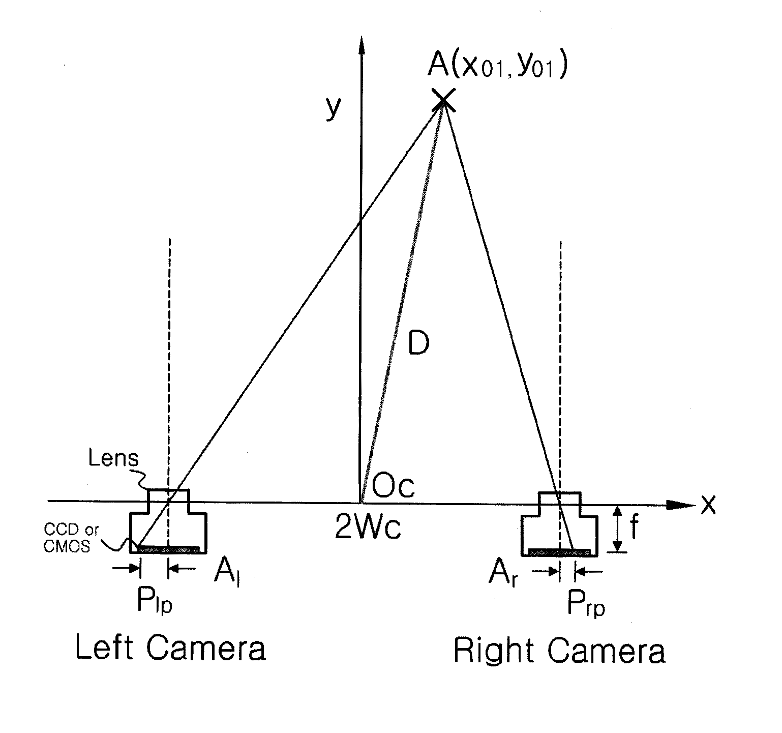
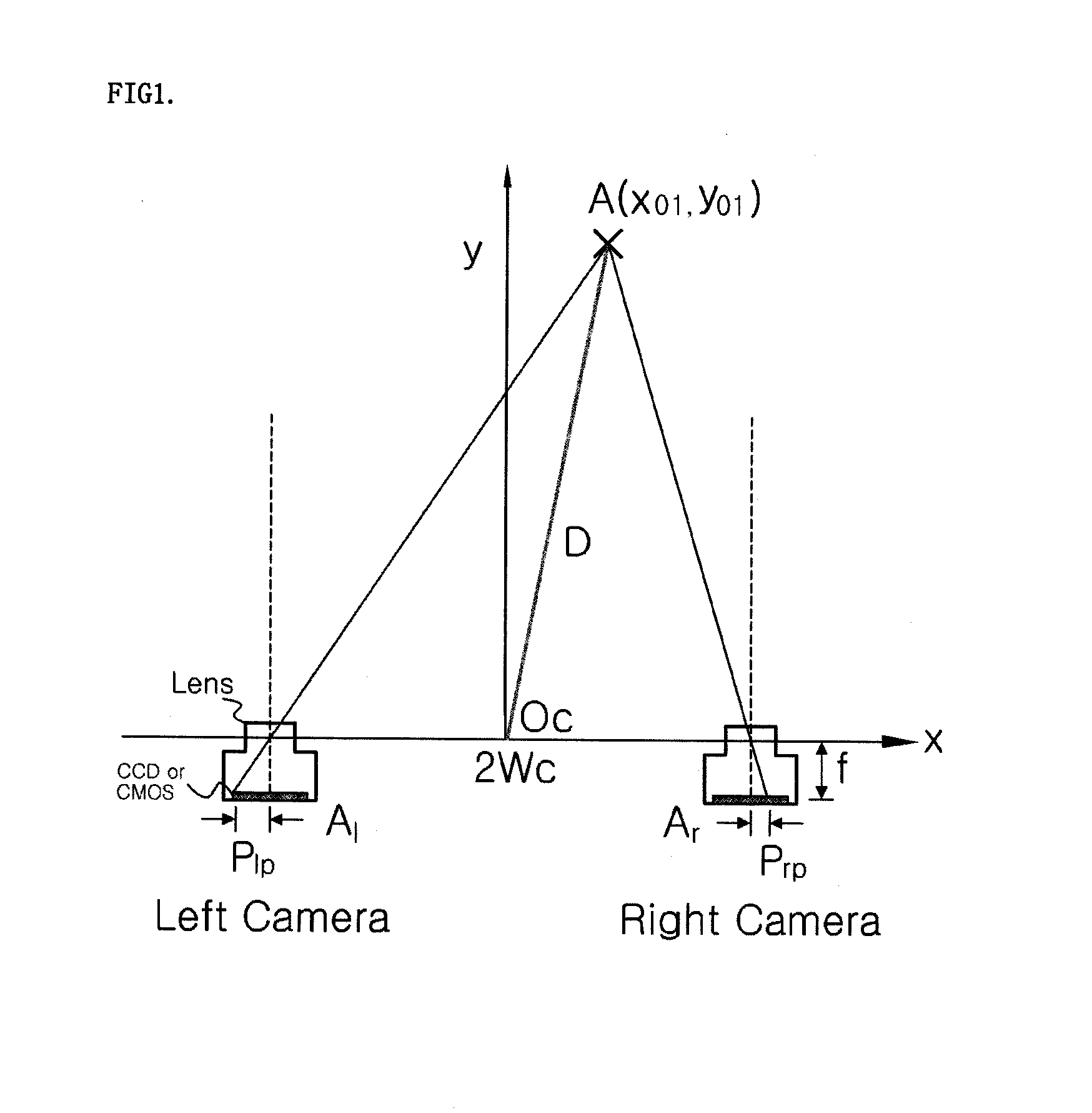
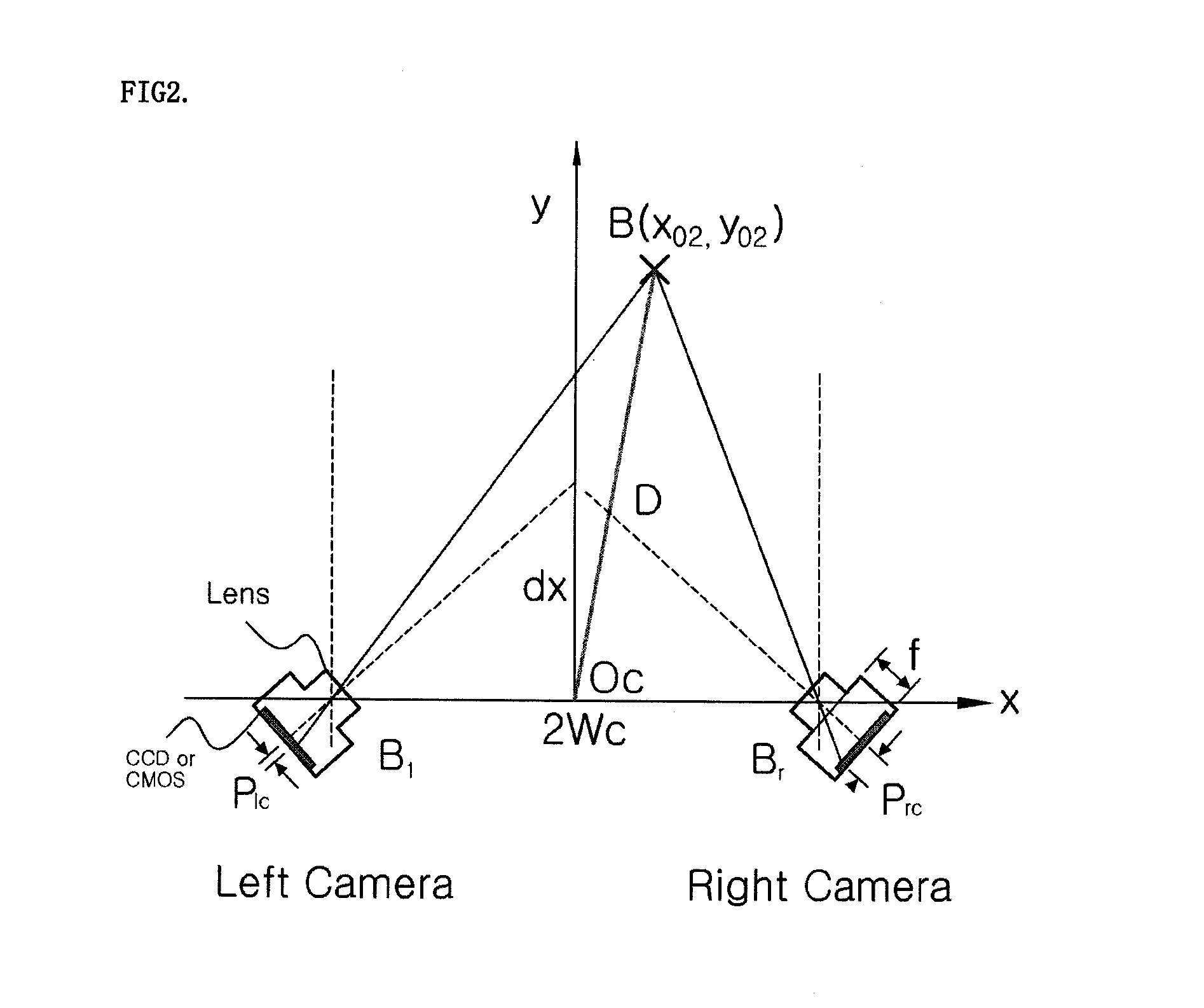
TECHNICAL FIELD[0001]The present invention relates to an image sensor for generating stereoscopic images, and more specifically, to a wafer-level image sensor for generating stereoscopic images, which facilitates mechanical alignment and is suitable for miniaturization.BACKGROUND ART[0002]Stereo vision arises from binocular disparity, in which the left / right eyes' different positions (the difference: 6.5 cm) leads to two different projections onto the retinas of the two eyes even when the same subject is viewed.[0003]Generally, stereo camera systems, which mechanically align two 2-dimensional (2-D) cameras, where an optical system is added to each of two image sensors that are independently manufactured, are required to generate stereoscopic images. Stereo camera systems are classified into parallel, convergence, and horizontal-moving stereo camera systems according to methods of aligning two cameras.[0004]FIG. 1 is a view illustrating a parallel stereo camera system.[0005]Referring...

Claims


Application Information

Patent Timeline
Patent Type & Authority Applications(United States)
IPC IPC(8): H04N13/02
CPCH01L27/14618H04N5/2253H04N13/0239H04N5/374H04N5/376H04N5/372H01L2224/48227H01L2224/49171H04N13/239H04N23/54H04N25/74H04N25/71H04N25/76H04N13/00
Inventor PARK, EUN HWAKANG, HIE MINN
Owner ASIC BANK CO LTD
Why Eureka
Try Eureka