Roller shutter type storage container
a storage container and roller shutter technology, applied in the direction of shutters/movable grilles, dismountable cabinets, door/window protective devices, etc., can solve the problems of deteriorating the operational sensation, excessive sliding resistance in the curved portion of the guide groove, and loading on the sliding operation of the roller shutter. , to achieve the effect of improving the operational sensation
- Summary
- Abstract
- Description
- Claims
- Application Information
AI Technical Summary
Benefits of technology
Problems solved by technology
Method used
Image

Examples
first embodiment
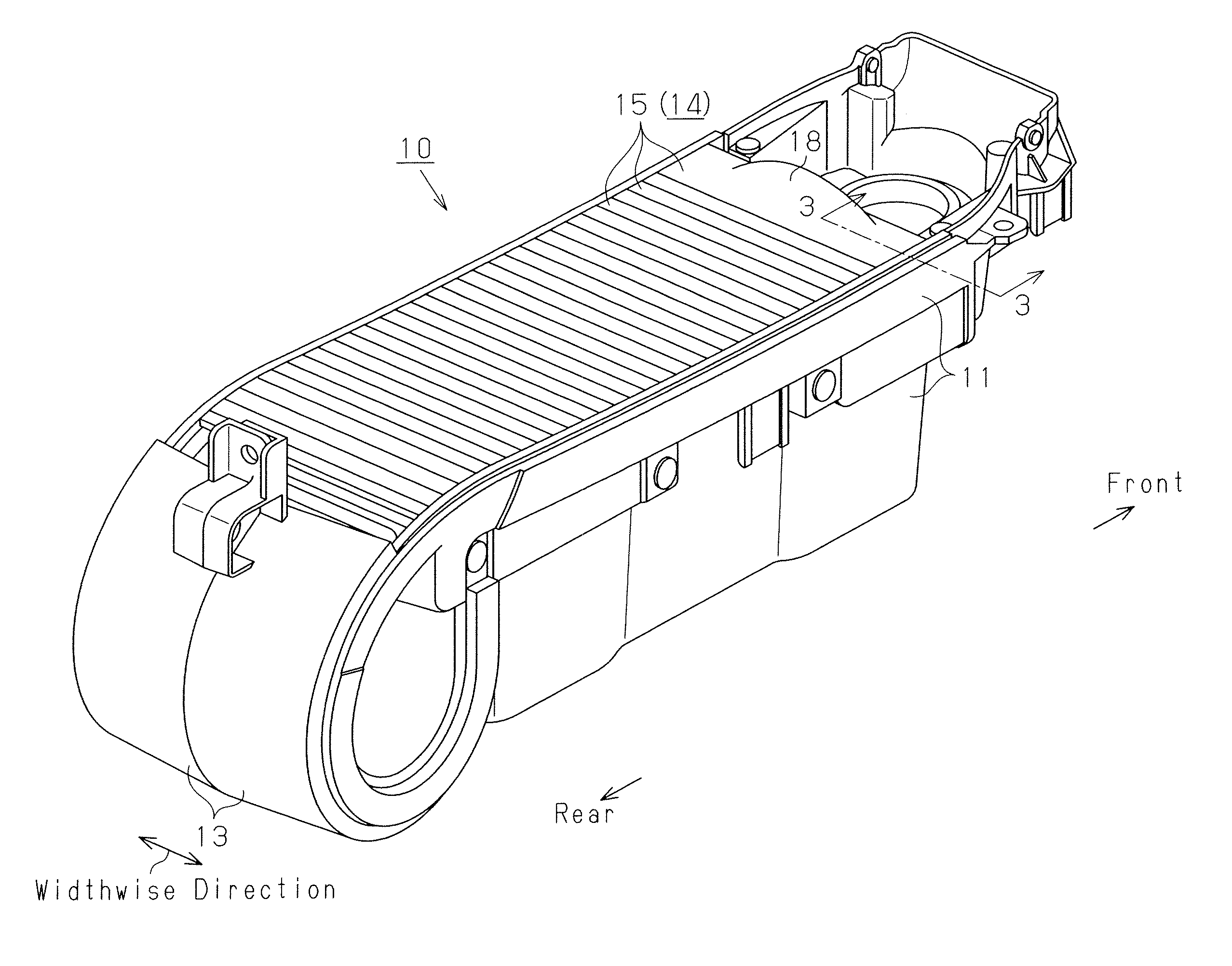
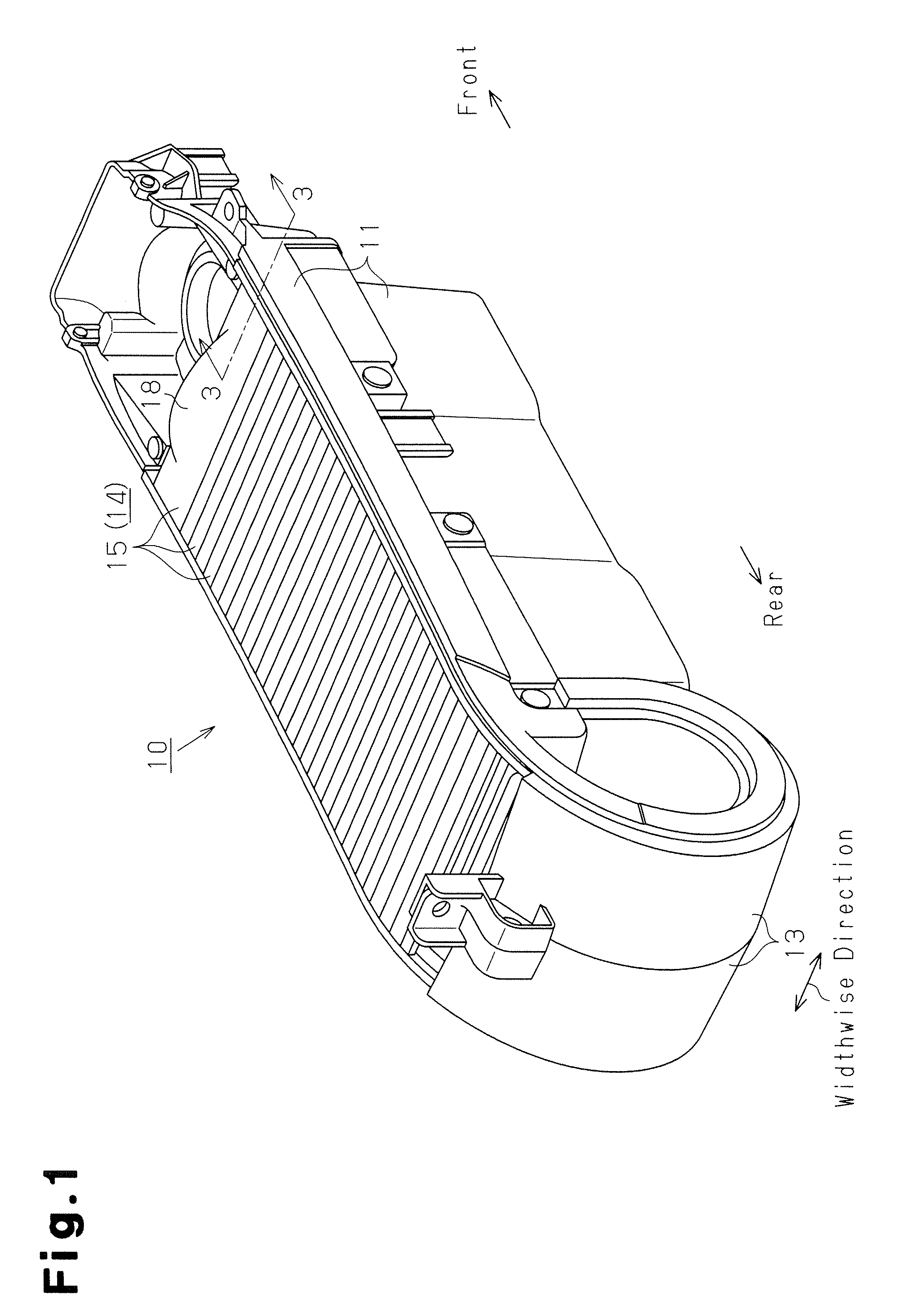
[0038]A first embodiment of a roller shutter type storage container according to the present invention, which is mounted in a center console of a vehicle, will now be described with reference to FIGS. 1 to 8. For the description below, the proceeding (advancing) direction of the vehicle is defined as the forward direction and the reverse direction of the vehicle is defined as the rearward direction.
[0039]A center console is arranged on the floor at a position between the driver's seat and the adjacent passenger seat in a vehicle. Operational portions such as a shift lever and a parking brake lever are provided in the center console. A roller shutter type storage container 10, which is shown in FIGS. 1 and 2, is also mounted in the center console.
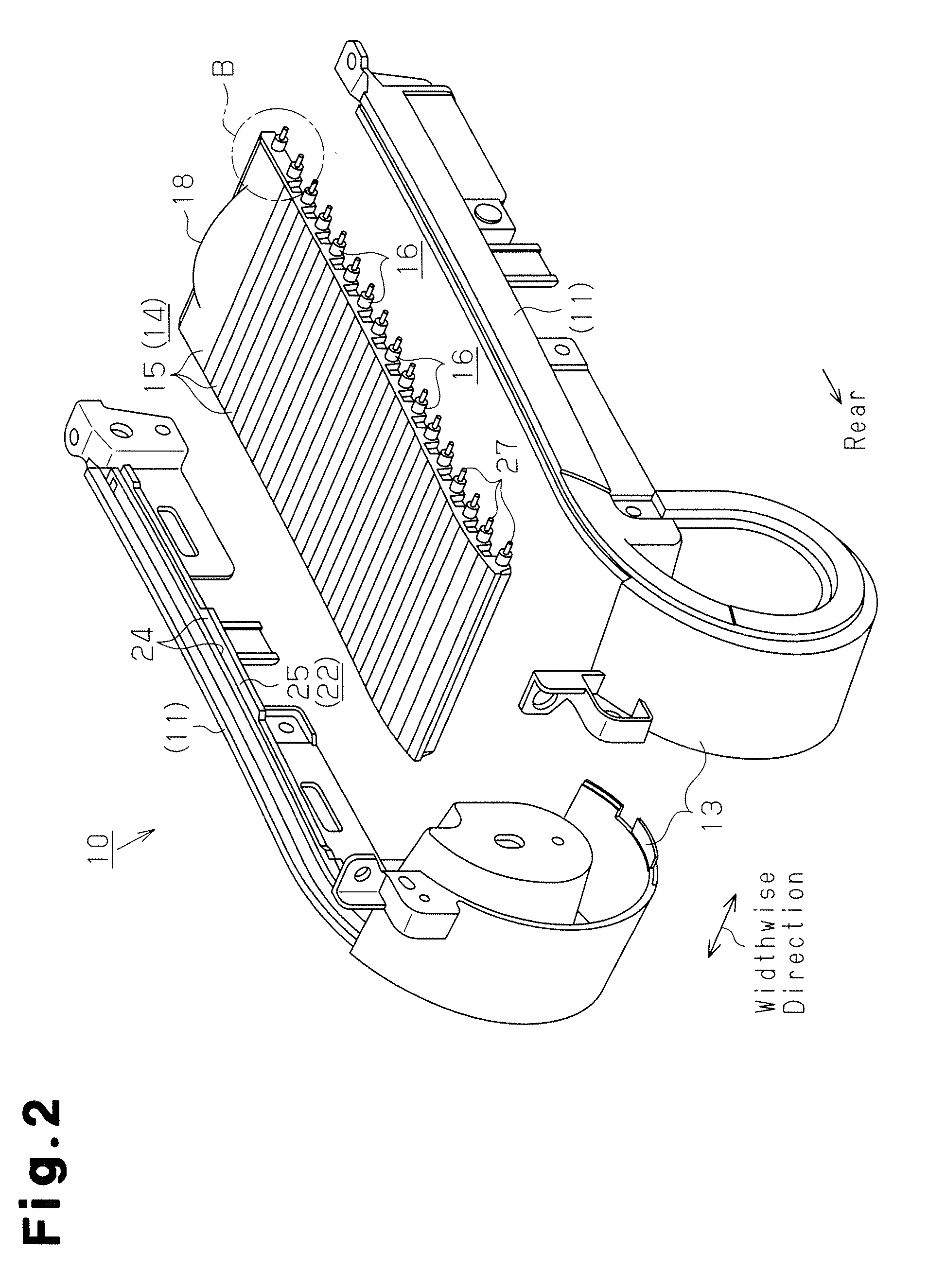
[0040]The roller shutter type storage container 10 includes a container body 11, a roller shutter accommodating portion 13, a pair of guide grooves 22, and a roller shutter 14.
[0041]The container body 11 accommodates, for example, drink cont...
second embodiment
[0071]A roller shutter type storage container according to a second embodiment of the present invention will hereafter be described with reference to FIGS. 9 to 11.
[0072]The second embodiment is different from the first embodiment in terms of the shape of each shaft 16 and the configuration of a projection 31.
[0073]In the first embodiment, the outer peripheral surface of each shaft 16 as a whole is configured by the curved surface 16A (FIG. 7). Contrastingly, in the second embodiment, as illustrated in FIG. 10B, the portions of each shaft 16 that contact the lateral wall surfaces 24 of the corresponding guide groove 22, which are two opposing portions, are each formed by a curved surface 16B. In the outer peripheral surface of each shaft 16, the two portions between the two curved surfaces 16B are configured by opposing parallel flat surfaces 16C.
[0074]With reference to FIG. 10B, unlike the projections 27 of the first embodiment having a rod-like shape, each of the projections 31 of...
third embodiment
[0081]A roller shutter type storage container according to a third embodiment of the present invention will now be described with reference to FIG. 12.
[0082]In the third embodiment, the lateral wall surfaces 24 of the guide grooves 22 are subjected to surface roughening to increase surface roughness, or, in other words, form rough surfaces. As the surface roughening, honing or graining, for example, is employed. After the surface roughening, grease is applied on the lateral wall surfaces 24.
[0083]The configuration of the components other than the lateral wall surfaces 24 of the third embodiment is identical to the corresponding configuration of the first embodiment. Same or like reference numerals are given to portions and components of the third embodiment that are the same as or like corresponding portions and components of the first embodiment. Detailed description of the portions and components are omitted herein.
[0084]In the configuration in which the shafts 16 slide in the gui...
PUM
 Abstract
Description
Claims
Application Information
 - R&D
- Intellectual Property
- Life Sciences
- Materials
- Tech Scout
- Unparalleled Data Quality
- Higher Quality Content
- 60% Fewer Hallucinations
Browse by: Latest US Patents, China's latest patents, Technical Efficacy Thesaurus, Application Domain, Technology Topic, Popular Technical Reports.
© 2025 PatSnap. All rights reserved.Legal|Privacy policy|Modern Slavery Act Transparency Statement|Sitemap|About US| Contact US: help@patsnap.com