Payload door and elevator system

a payload door and elevator technology, applied in the field of payload doors and elevator systems, can solve the problems of increasing weight and deployment times, unable to support the device on the corners of the mounting plate, and sensitive to vibration of the mounted payload of this typ

Inactive Publication Date: 2012-02-02
JORGENSEN JAMES +1
View PDF2 Cites 15 Cited by
  • Summary
  • Abstract
  • Description
  • Claims
  • Application Information

AI Technical Summary

Benefits of technology

[0028]It is yet another object of the invention to translate such a payload...

Problems solved by technology

In such designs, with support only provided at one end, the mounted payload of this type is sensitive to vibration, especially when deployed at high airspeeds.
This increases weight and deployment times and has other disadvantages.
This causes the local pressure to try and pull the doors of the assembly away from or out of the fuselage.
The deployed doors in the high speed airstream can also cause problems by redirecting the moving air into the payload.
The device, however, does not offer support on the corners of the mounting plate as would be need...

Method used


Image

  • Payload door and elevator system
  • Payload door and elevator system
  • Payload door and elevator system

Examples


Embodiment Construction

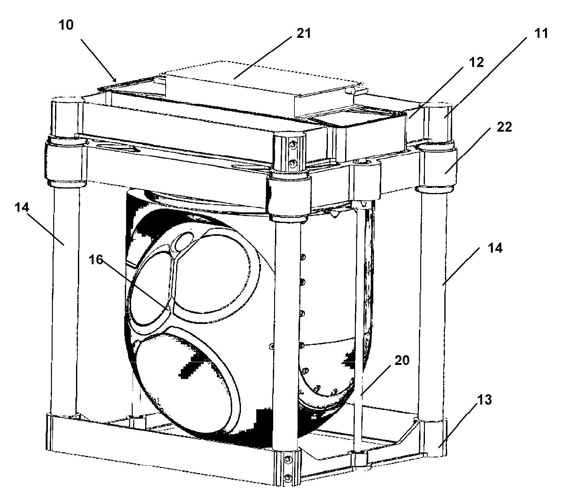
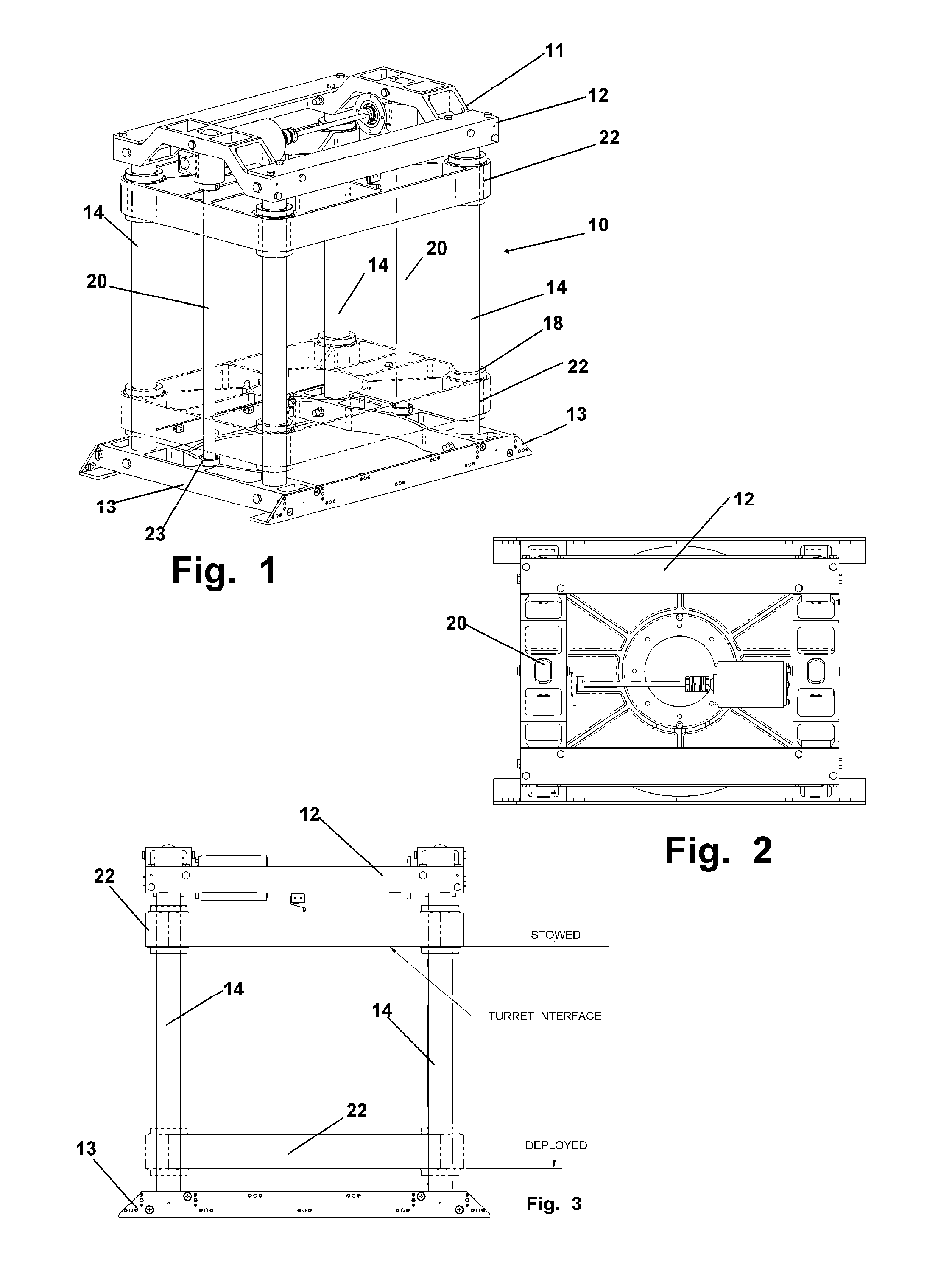
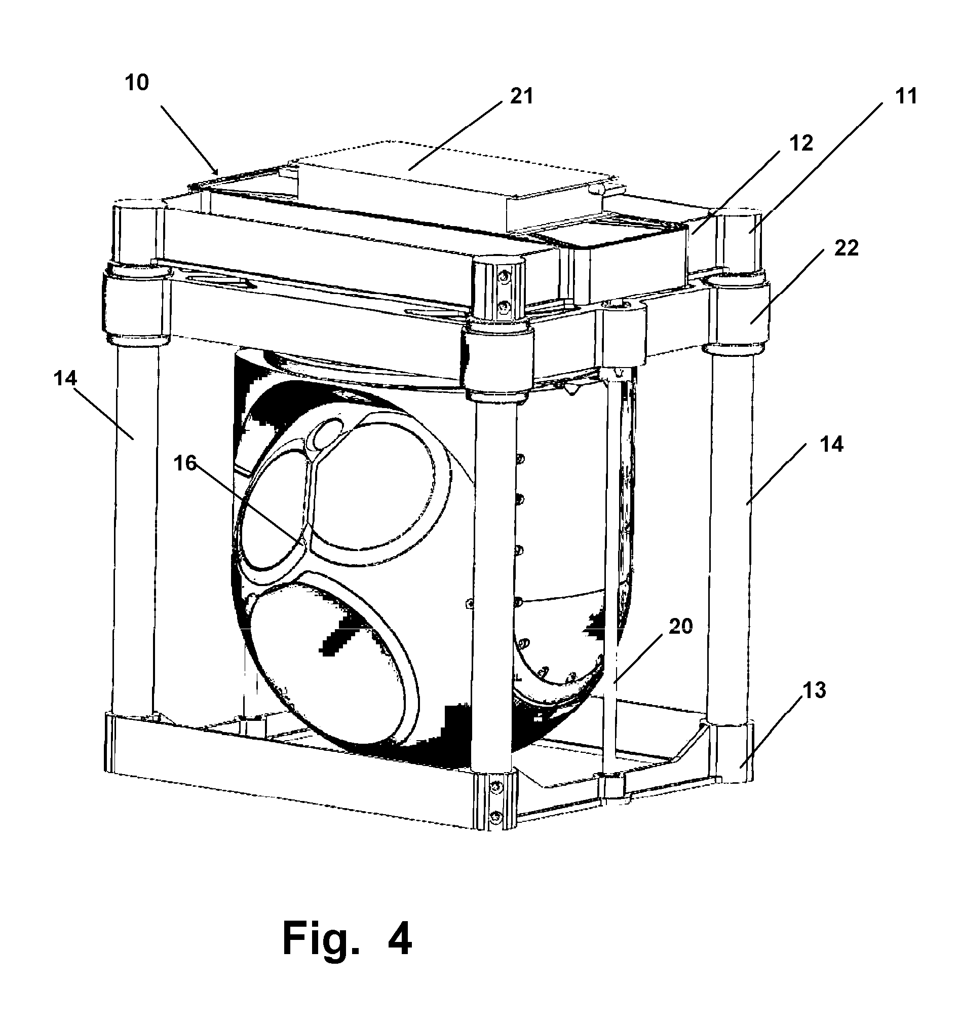
[0038]Now referring to drawings in FIGS. 1-11, wherein similar components are identified by like reference numerals, there is seen in FIG. 1 an embodiment of the invention 10 depicting the payload translation component 11 and showing the engagement of a payload 16, such as a rotatable camera, to the mounting plate 22. The members forming the support shafts 14 are positioned at the corners of the top 12 and bottom 13 plates and are rigidly engaged to the top 12 and bottom 13 plates respectively.

[0039]The translatable mounting plate member 22 is positioned between the top 12 and bottom 13 plates and engaged via sliding bushings 18 to a translatable engagement to the support shafts 14. These bushings 18 allow for translation only along the axial direction of the support shafts 14.

[0040]The lead actuating screws 20, such as worm gears, are positioned symmetrically for rotational engagement between the opposite edges of the top 12 and bottom 13 plates and are engaged on either plate by a...


PUM


Abstract

A payload door and elevator system for the translation of a payload such as a camera, from a stowed position within an aircraft fuselage to a deployed position projecting through an aperture formed in the wall of the fuselage. The system employs a translation component engaged to vertically translate the payload and operatively positioned inline with the aperture. Payload doors sealing the aperture horizontally translate in opposing directions once vertically translated from sealed engagement with the aperture. The horizontal translation alleviates much of the stress imparted to doors on aircraft which move to vertical positions in or extending from the aperture in the fuselage.

Description

[0001]This application claims priority to U.S. Provisional Application Ser. No. 61 / 364963, filed on Jul. 16, 2010, and is incorporated in its entirety by reference herein.BACKGROUND OF THE INVENTION[0002]1. Field of the Invention[0003]The disclosed device relates to aircraft bay elevator systems. More specifically, to a system and method for deploying a payload, which employs doors, which translate and retract into the fuselage, and a payload translation system employing a non-cantilevered elevator design which symmetrically supports the payload at both ends.[0004]2. Prior Art[0005]National security has become more important since the events of 9 / 11. Many measures in ensuring safety have been employed such as increased border and air traffic security, weapons detection and recovery, as well as enemy surveillance and many others. Surveillance, especially that done by aircraft, effectively scouts dangerous territory and with the assistance of unmanned areal vehicles, can reduce the po...

Claims


Application Information

Patent Timeline
IPC IPC(8): B64C1/14B64D47/08B64C7/00
CPCB64D47/08
Inventor JORGENSEN, JAMESCAMPBELL, SCOTT
Owner JORGENSEN JAMES
Why Eureka
Try Eureka