Fuel injector having pressure sensor

a technology of pressure sensor and fuel injector, which is applied in the direction of liquid fuel feeder, machine/engine, mechanical apparatus, etc., can solve the problems of pressure sensor being something of a problem, laborious and cost-intensive components, etc., and achieves easy and inexpensive production, short operating times, and easy transmission of pressure

Active Publication Date: 2012-02-09
ROBERT BOSCH GMBH
View PDF3 Cites 8 Cited by
  • Summary
  • Abstract
  • Description
  • Claims
  • Application Information

AI Technical Summary

Benefits of technology

[0002]An object of the present invention is to provide a simple and inexpensive device for measuring the fuel pressure in a fuel injection system.

Problems solved by technology

The pressure sensors therefore have to be sealed off from the high pressure of the fuel in the injection system and thus constitute an elaborate and cost-intensive component.
Furthermore, finding a suitable location at which to fit the pressure sensor is something of a problem in systems having no central pressure accumulator.

Method used


Image

  • Fuel injector having pressure sensor
  • Fuel injector having pressure sensor
  • Fuel injector having pressure sensor

Examples


Embodiment Construction

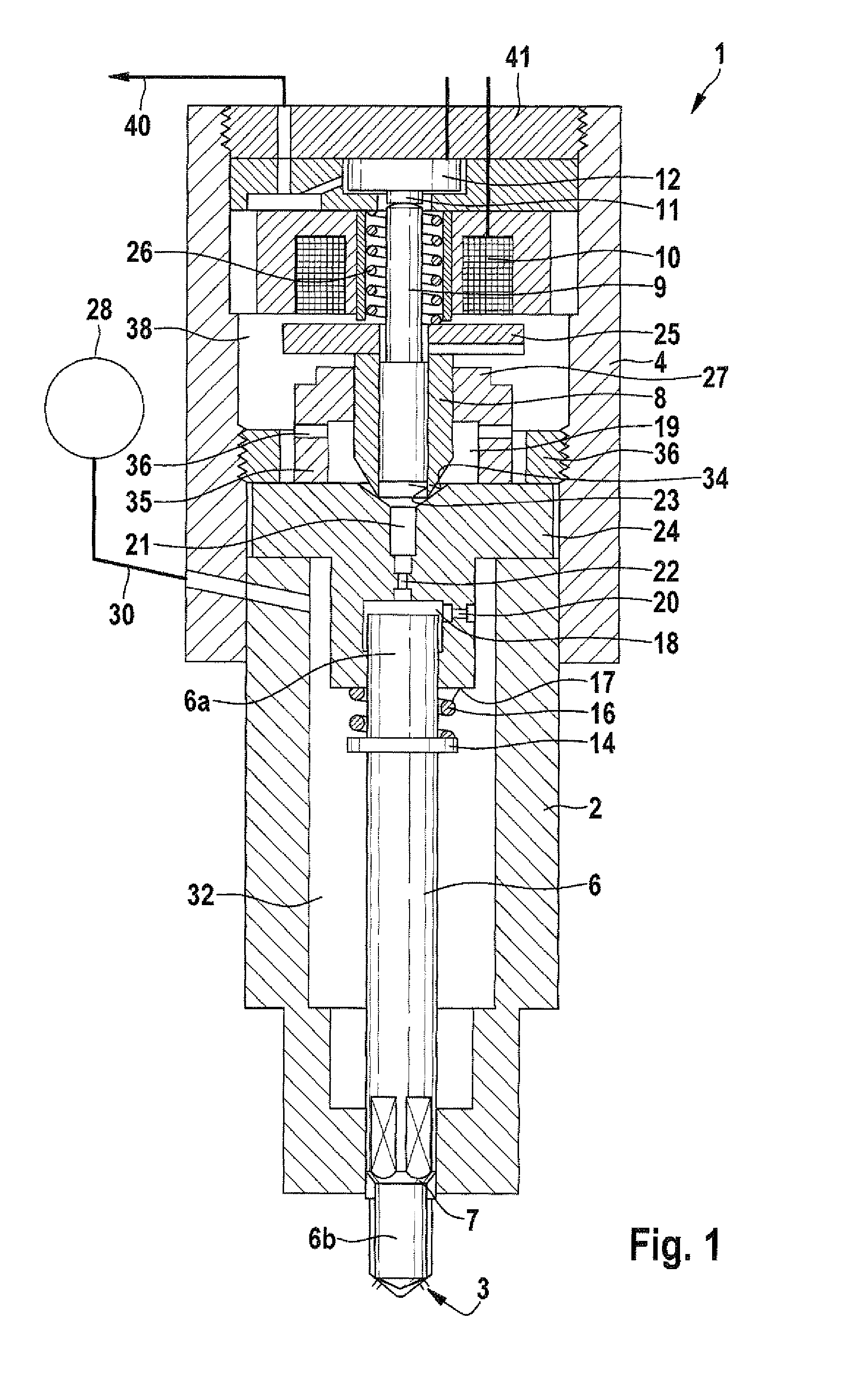
[0018]FIG. 1 shows a sectional representation of a fuel injector 1 according to the invention. The fuel injector 1 comprises a cylindrical nozzle body 2 shown in the lower area of FIG. 1, and a cylindrical union nut 4, which is arranged above the nozzle body 2 and is tightly screwed to the nozzle body 2. At its end shown at the top in FIG. 1, the injector 1 is closed by a closure plate 41, which is screwed hydraulically tight to the union nut 4.

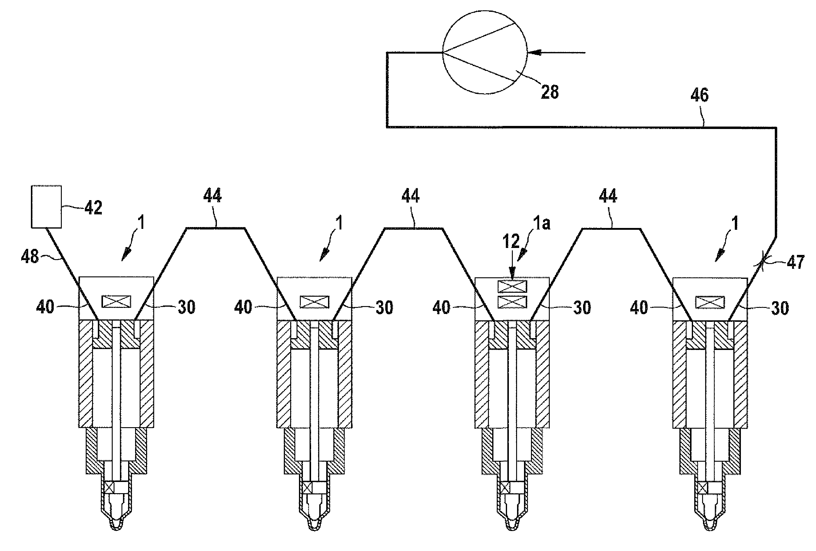
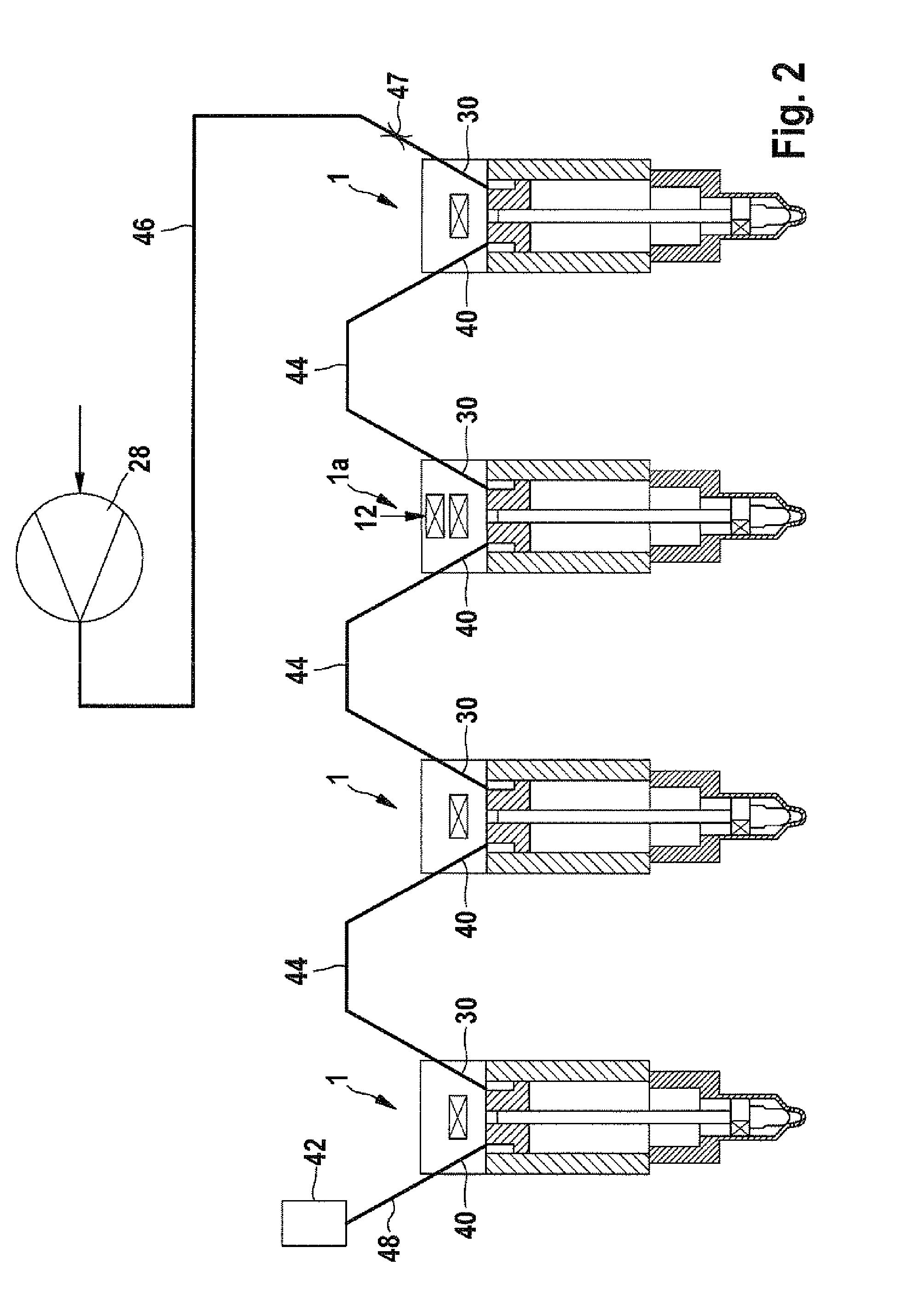
[0019]A high-pressure chamber 32, which by way of a fuel inlet 30 can be filled by an external fuel pump 28 with fuel under high pressure, is formed inside the nozzle body 2.

[0020]Injection ports 3, through which fuel can flow from the high-pressure chamber 32 into a combustion chamber (not shown), which encloses the lower end of the nozzle body 2, are formed at the end of the nozzle body 2 shown at the bottom of FIG. 1.

[0021]The upper end of the high-pressure chamber 32 situated opposite the injection ports 3 is defined by a valve plate 24, ...


PUM


Abstract

The invention relates to a fuel injector (1) having a high pressure region (32) which contains fuel that is under high pressure during operation, and a low pressure region (38) in which a lower pressure is present during operation than in the high pressure region (32). A sensor (12) is located in the low pressure region (38) and a transmission means (9) is arranged such that a force which is equal to the pressure of the fuel in the high pressure region (32) is exerted on the sensor (12) at least some of the time.

Description

BACKGROUND OF THE INVENTION[0001]Pressure sensors in fuel injection systems for measuring the fuel pressure are known in the state of the art. Such known pressure sensors are generally arranged in a central pressure accumulator of the injection system where they are subjected to the high pressure of the fuel in the injection system. In modern common rail systems the fuel pressure may be a few thousand bar. The pressure sensors therefore have to be sealed off from the high pressure of the fuel in the injection system and thus constitute an elaborate and cost-intensive component. Furthermore, finding a suitable location at which to fit the pressure sensor is something of a problem in systems having no central pressure accumulator.SUMMARY OF THE INVENTION[0002]An object of the present invention is to provide a simple and inexpensive device for measuring the fuel pressure in a fuel injection system.[0003]This object is achieved by a fuel injector as claimed in the independent claim 1. A...

Claims


Application Information

Patent Timeline
Patent Type & Authority Applications(United States)
IPC IPC(8): F02M69/04
CPCF02M47/027F02M57/005F02M2200/24F02M63/008F02M63/0026
Inventor MAGEL, HANS-CHRISTOPH
Owner ROBERT BOSCH GMBH
Why Eureka
Try Eureka