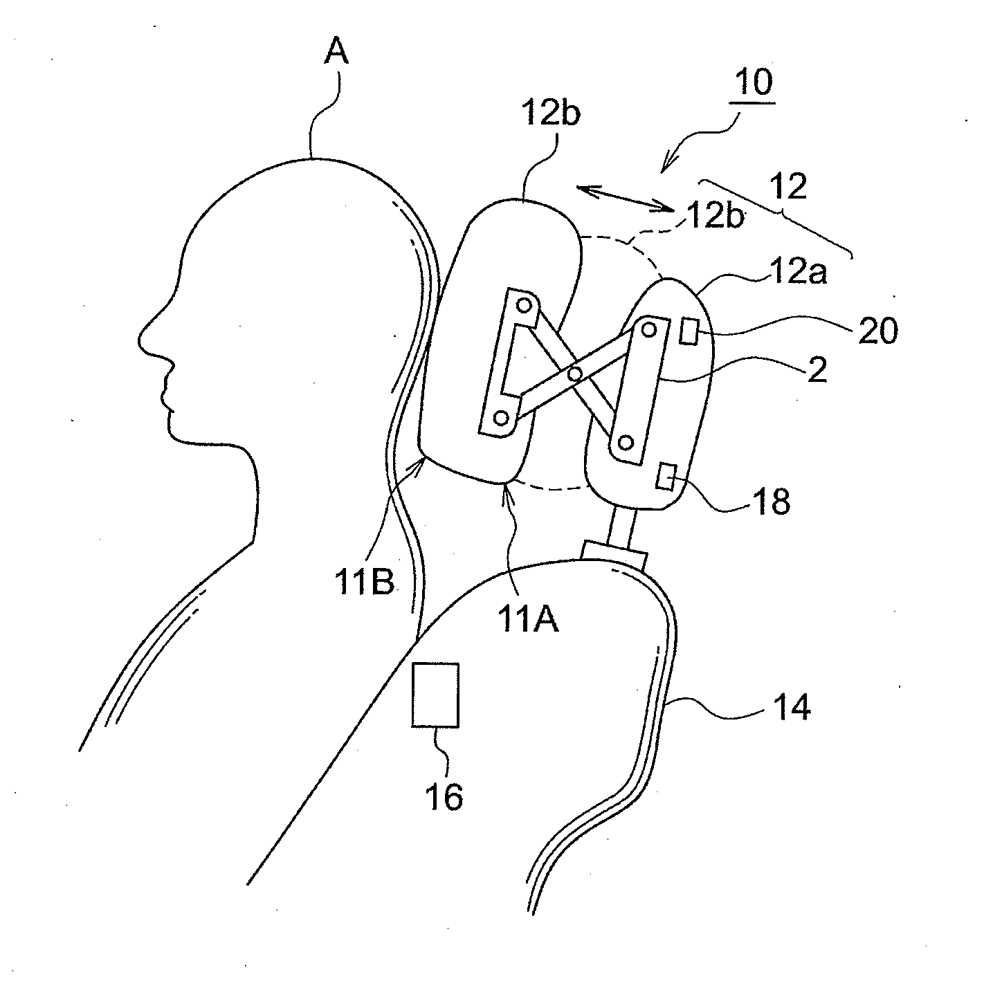
Headrest device, method of adjusting headrest positiion, and vehicle seat
- Summary
- Abstract
- Description
- Claims
- Application Information
AI Technical Summary
Benefits of technology
Problems solved by technology
Method used
Image

Examples
fourth exemplary embodiment
[0131]Note that, although the fourth exemplary embodiment describes a case in which the pressure value is detected plural times in the first exemplary embodiment, the fourth exemplary embodiment can be applied in the same way to the second and third exemplary embodiments as well.
[0132]Further, instead of detecting the pressure value plural times, the pressure value may be detected again after a predetermined time elapses from the initial detection of the pressure value, and the position of the headrest may be controlled when the difference between the pressure value that was initially detected and the pressure value that was detected again becomes within a predetermined value. In this case as well, effects that are similar to those of the fourth exemplary embodiment are obtained.
[0133]A headrest device of a fifth exemplary embodiment is described next. In the fifth exemplary embodiment, the position of the headrest is adjusted again not only when the passenger sits in the seat, but ...
fifth exemplary embodiment
[0138]Note that, although the fifth exemplary embodiment describes a case in which the pressure value is always monitored in the first exemplary embodiment, the fifth exemplary embodiment can similarly be applied to the second through fourth exemplary embodiments as well.
[0139]Further, the respective exemplary embodiments describe cases in which the pressure that is applied to the seat back is detected by using a pressure sensor sheet that is disposed over the entire surface of the vehicle front side of the seat back. However, there may be a structure in which pressure sensors are disposed at plural places at the vehicle front side of the seat back. Note that the position at which the pressure sensor is placed can be made to be a position that is at a height in the vicinity of the back portion of the passenger, and that is at the center of or at the left and right of the seat back. In particular, as shown in FIG. 19, it is preferable for the position to be a position that includes a...
PUM
 Abstract
Description
Claims
Application Information
 - Generate Ideas
- Intellectual Property
- Life Sciences
- Materials
- Tech Scout
- Unparalleled Data Quality
- Higher Quality Content
- 60% Fewer Hallucinations
Browse by: Latest US Patents, China's latest patents, Technical Efficacy Thesaurus, Application Domain, Technology Topic, Popular Technical Reports.
© 2025 PatSnap. All rights reserved.Legal|Privacy policy|Modern Slavery Act Transparency Statement|Sitemap|About US| Contact US: help@patsnap.com