Portable light energy utilization structure

A portable, light-energy technology, applied in the support structure of photovoltaic modules, photovoltaic modules, photovoltaic power generation, etc., can solve the problems of inconvenient movement, inconvenience to carry, and time-consuming, and achieve convenient production, improved portability, lightening The effect of weight

Pending Publication Date: 2021-11-30
浙江腾圣储能技术有限公司
View PDF1 Cites 0 Cited by
  • Summary
  • Abstract
  • Description
  • Claims
  • Application Information

AI Technical Summary

Problems solved by technology

[0002] Photovoltaic AC power generation device is a device used in a photovoltaic power generation system to absorb and convert solar energy into DC power and then convert it into AC power. It is widely used. The existing solar AC power generation device includes solar panels and inverters. It has become an important part of human energy use and has been continuously developed; but on the one hand, when the existing photovoltaic power generation AC devices are in use, the photovoltaic panels are mostly fixed structures. And it is heavy and inconvenient to move; on the other hand, the existing photovoltaic power generation AC devices are usually installed directly on special photovoltaic brackets, but similar photovoltaic devices require professional construction personnel to complete the installation process, which takes a lot of time. The flexibility is very poor, so it has high practical value and significance to propose a portable light energy utilization structure
[0003] Patent document CN108964582A discloses a photovoltaic system, comprising: a photovoltaic module for absorbing solar energy and converting the solar energy into DC power; a solar ray incident angle measuring device for measuring the incident angle of the solar ray irradiated on the photovoltaic module; The self-adjusting bracket under the photovoltaic module is used to change its orientation and inclination angle with the change of the incident angle of the sun's rays; the inverter is connected to the photovoltaic module to convert the DC power into AC power After the grid-connected output; the controller is connected with the solar ray incident angle measurement device, the automatic adjustment bracket and the inverter respectively, but this design is inconvenient to disassemble and carry, and the structure is unreasonable

Method used


Image

  • Portable light energy utilization structure
  • Portable light energy utilization structure
  • Portable light energy utilization structure

Examples


Embodiment Construction

[0040] The present invention will be described in detail below in conjunction with specific embodiments. The following examples will help those skilled in the art to further understand the present invention, but do not limit the present invention in any form. It should be noted that those skilled in the art can make several changes and improvements without departing from the concept of the present invention. These all belong to the protection scope of the present invention.

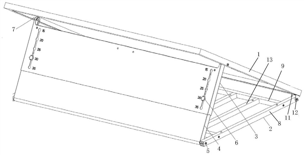
[0041] A kind of portable light energy utilization structure provided according to the present invention, such as figure 1 As shown, it includes a photovoltaic body 1, a supporting device and a base body 2, the base body 2 is a frame structure, and the two ends of the base body 2 are respectively provided with a first beam 8 and two first beams 8 Parallel to each other, one end of the photovoltaic body 1 is rotatably mounted on one end of the two first beams 8, and the other end of the photovoltaic body...


PUM

PropertyMeasurementUnit
lengthaaaaaaaaaa
widthaaaaaaaaaa
thicknessaaaaaaaaaa

Abstract

The invention provides a portable light energy utilization structure, and belongs to the photovoltaic technical field. The structure comprises a photovoltaic body, a support device and a base body; the base body is a frame type structure, two ends of the base body are respectively provided with a first cross beam, and the two first cross beams are parallel to each other; one end of the photovoltaic body is rotatably mounted at one ends of the two first cross beams, the other end of the photovoltaic body is connected with the other ends of the two first cross beams through a supporting device, and the photovoltaic body can be switched between a supporting state and a storage state by adjusting the supporting device; the first cross beam, the third cross beam and the second cross beam are each of a tubular structure, the weight of the device is greatly reduced, the structure is simple, installation is convenient, and the portability and use universality of the device are improved.

Description

technical field [0001] The invention relates to the field of photovoltaic technology, in particular to a portable light energy utilization structure. Background technique [0002] Photovoltaic AC power generation device is a device used in a photovoltaic power generation system to absorb and convert solar energy into DC power and then convert it into AC power. It is widely used. The existing solar AC power generation device includes solar panels and inverters. It has become an important part of human energy use and has been continuously developed; but on the one hand, when the existing photovoltaic power generation AC devices are in use, the photovoltaic panels are mostly fixed structures. And it is heavy and inconvenient to move; on the other hand, the existing photovoltaic power generation AC devices are usually installed directly on special photovoltaic brackets, but similar photovoltaic devices require professional construction personnel to complete the installation proc...

Claims


Application Information

Patent Timeline
Patent Type & Authority Applications(China)
IPC IPC(8): H02S20/30F24S25/13F24S30/425
CPCH02S20/30F24S25/13F24S30/425Y02E10/47Y02E10/50
Inventor 不公告发明人
Owner 浙江腾圣储能技术有限公司
Why Eureka
Try Eureka