Large and small pumps simultaneously strong backflow and large and small pumps inject compound pump valve at the same time

A composite pump and spool technology, applied in pumps, pump components, pump devices, etc., can solve problems such as clogging, loss of a large number of injection channels, and anti-blocking and reduction of backflow of a small amount of injection channels, so as to reduce manufacturing costs, Effect of reducing wear and increasing service life

Active Publication Date: 2020-02-11
ZHENGZHOU SANHUA TECH & IND
View PDF8 Cites 0 Cited by
  • Summary
  • Abstract
  • Description
  • Claims
  • Application Information

AI Technical Summary

Problems solved by technology

However, when encountering a viscous fluid, when the compound pump injects the step, that is, when the valve core is in the initial position of closing the color paste injection, the color paste in the color paste bucket can be sucked into the compound pump or discharged from the compound pump. Press the color paste back into the color paste bucket, a considerable part of the viscous liquid flows back to the color paste bucket from the short circuit, but the viscous color paste does not pass through completely, or does not pass through a large number of injection channels and a small amount of injection channels state, which reduces or loses the anti-blocking effect of a large number of injection channels and a small amount of injection channels, so there is a risk of blockage of a large number of injection channels or a small amount of injection channels

Method used


Image

  • Large and small pumps simultaneously strong backflow and large and small pumps inject compound pump valve at the same time
  • Large and small pumps simultaneously strong backflow and large and small pumps inject compound pump valve at the same time
  • Large and small pumps simultaneously strong backflow and large and small pumps inject compound pump valve at the same time

Examples


Embodiment Construction

[0054] Below in conjunction with accompanying drawing, specific embodiment of the present invention is described in further detail:

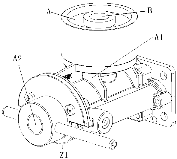
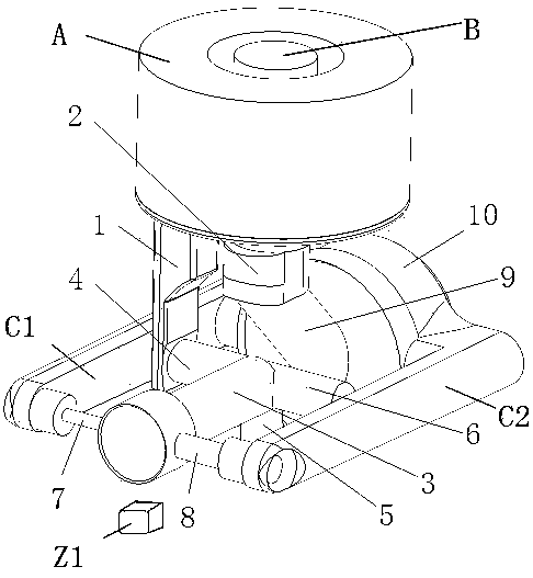
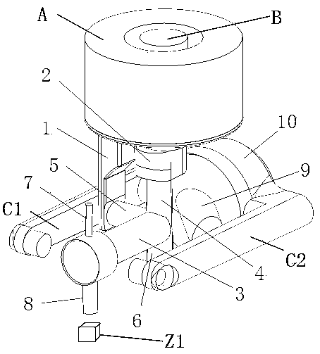
[0055] like Figure 1-Figure 41 As shown, the large and small pumps have strong backflow at the same time and the large and small pumps simultaneously inject the composite pump valve, a pump valve structure that prevents viscous liquid from clogging the injection channel, including large and small pumps with a piston structure. The large and small pumps with a piston structure are A small pump cavity is provided at the bottom of the outlet in the large pump cavity, and a small piston protrudes from the end face of the large piston in the large pump cavity. The small piston and the small pump cavity form a small pump, and the large pump and the small pump form a compound pump; And the control valve for controlling the circulation of large and small composite pumps. The control valve includes a valve body and a valve core. The valve body is provid...


PUM


Abstract

A combination pump valve with a large-small pump for simultaneous powerful backflow and outpouring includes the large-small pump which is of a piston structure and a control valve for controlling circulation of a large pump, a small pump and a combination pump. The large-small pump which is of a piston structure is that a small pump cavity body is arranged at the bottom end of an outlet in a cavity body of the large pump, a small piston extends out of the end face of a large piston in the cavity body of the large pump, the small pump is formed by a small piston and the cavity body of the smallpump, and the combination pump is formed by the large pump and the small pump; and the control valve includes a valve body and a valve core, the valve body is internally provided with a valve core cavity body which can accommodate rotation of the valve core, and the valve core is placed in the valve core cavity body. According to the combination pump valve with the large-small pump for the simultaneous powerful backflow and outpouring, powerful pressure of the combination pump during outpouring steps is adopted to dredge a large-amount outpouring channel and a small-amount outpouring channel,during implementation of the steps, vacuum of the combination pump can be supplemented in time, and long-time await for vacuum supplementation in the combination pump can be avoided.

Description

technical field [0001] The invention relates to the technical field of paint toning, in particular to a compound pump valve for simultaneous strong backflow of large and small pumps and simultaneous injection of large and small pumps. Background technique [0002] There are pump and valve structures already produced by our company, including large and small pumps with a plunger piston structure, valves for controlling the flow channels of large and small pumps, and a small pump cavity is installed at the bottom of the outlet of the large valve cavity, and extends inside the large pump cavity. A small piston is produced, and the small piston and the small pump cavity form a small pump, and the large pump and the small pump form a composite pump. The valve that controls the circulation of the large and small pumps includes such a flow structure. After the color paste pumped by the compound pump passes through the large amount of injection channel and the small amount of inject...

Claims


Application Information

Patent Timeline
Patent Type & Authority Patents(China)
IPC IPC(8): F04B15/02F04B23/06F04B53/10F04B53/16
CPCF04B15/02F04B23/06F04B53/10F04B53/16
Inventor 王保松黄松
Owner ZHENGZHOU SANHUA TECH & IND
Why Eureka
Try Eureka