
Image processing apparatus, image processing method, and computer readable medium

a technology of image processing which is applied in the field of image processing apparatus and image processing method, and the application of computer readable medium, can solve the problem that it takes a substantial time before a high-quality image is displayed, and achieve the effect of reducing blur and reducing blur

Active Publication Date: 2012-02-09
FUJIFILM CORP
View PDF6 Cites 37 Cited by
  • Summary
  • Abstract
  • Description
  • Claims
  • Application Information

AI Technical Summary

Benefits of technology

[0022]An arrangement is also possible in which the parameter determining section determines, respectively for the plurality of characteristic regions, the image processing parameters for reducing noise in the images of the plurality of characteristic regions, and the second image processing section generates the plurality of high quality characteristic-region images respectively resulting from reducing noise in the images of the plurality of characteristic regions, using the image processing parameters determined by the parameter determining section.
[0024]An arrangement is also possible in which the parameter determining section determines, respectively for the plurality of characteristic regions, the image processing parameters for reducing blur in the images of the plurality of characteristic regions, and the second image processing section generates the plurality of high quality characteristic-region images respectively resulting from reducing blur in the images of the plurality of characteristic regions, using the image processing parameters determined by the parameter determining section.

Problems solved by technology

In these techniques, unless the high image-quality processing is adequately selected for each characteristic region, it would takes a substantial time before a high-quality image is displayed because of a large operation amount.

Method used


Image

  • Image processing apparatus, image processing method, and computer readable medium
  • Image processing apparatus, image processing method, and computer readable medium
  • Image processing apparatus, image processing method, and computer readable medium

Examples


Embodiment Construction

[0044]Hereinafter, (some) embodiment(s) of the present invention will be described. The embodiment(s) do(es) not limit the invention according to the claims, and all the combinations of the features described in the embodiment(s) are not necessarily essential to means provided by aspects of the invention.

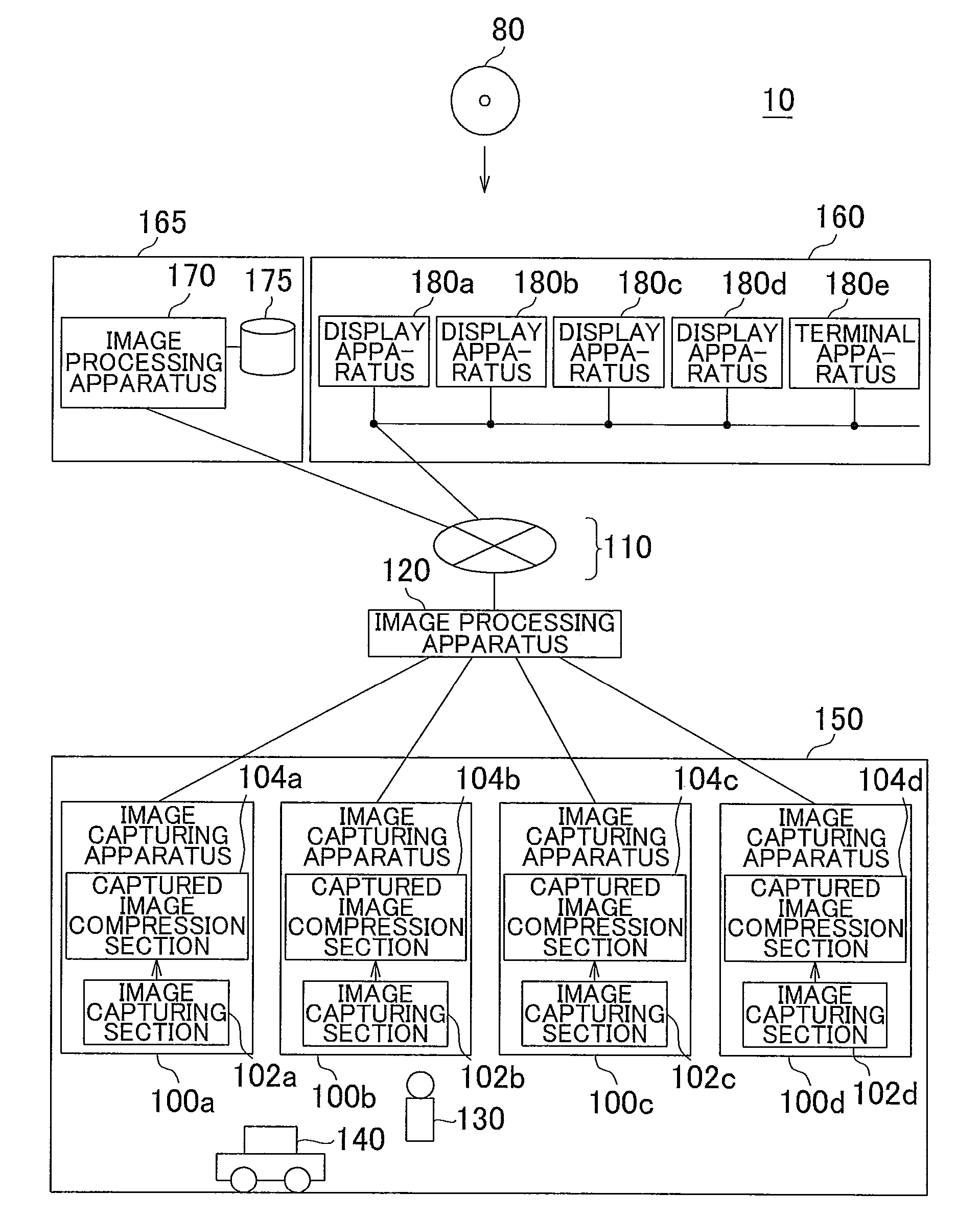
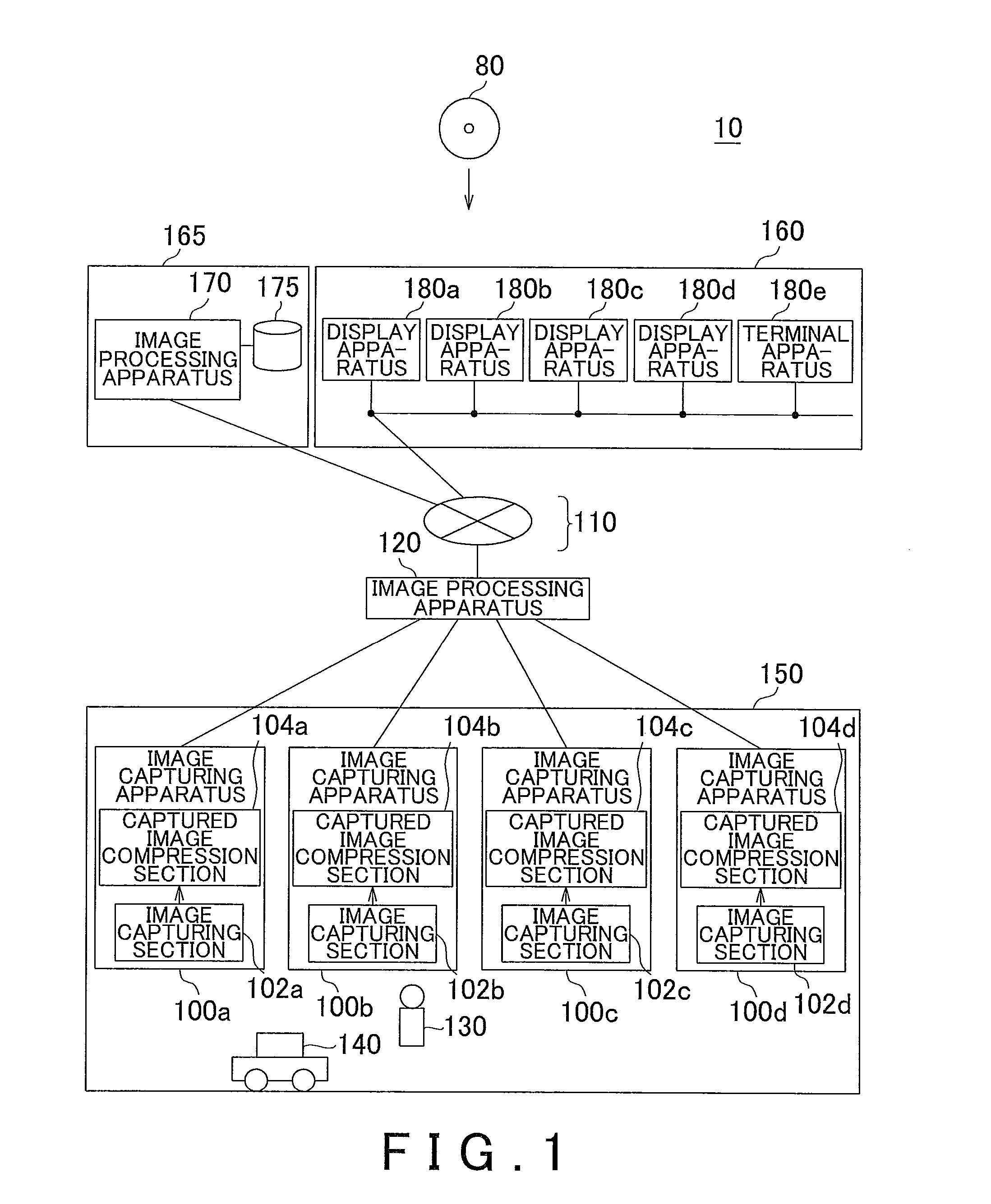
[0045]FIG. 1 shows an example of an image processing system 10 according to an embodiment. As explained below, the image processing system 10 can function as a monitoring system in an example.

[0046]The image processing system 10 includes a plurality of image capturing apparatuses 100a-d for capturing an image of a monitored space 150, an image processing apparatus 120 for processing the image captured by the image capturing apparatus 100, a communication network 110, an image processing apparatus 170, an image DB 175, and a plurality of display apparatuses 180a-d. The image processing apparatus 170 is provided in a space 165 different from the monitored space 150. The display appara...


PUM


Abstract

An image processing apparatus includes: an image obtaining section obtaining an input image; a first image processing section generating a predetermined quality image resulting from rendering the input image in high image quality using a predetermined image processing parameter; a display section displaying the predetermined quality image; a characteristic region identifying section identifying a plurality of characteristic regions in the input image; a parameter determining section determining, respectively for the plurality of characteristic regions, image processing parameters for rendering images of the plurality of characteristic regions, in higher image quality; a second image processing section generating a plurality of high quality characteristic-region images respectively of the plurality of characteristic regions, using the image processing parameters determined by the parameter determining section; and a display control section replacing the plurality of characteristic regions in the predetermined quality image under display, with the plurality of high quality characteristic-region images.

Description

[0001]The contents of the following International patent application is incorporated herein by reference:[0002]International Patent Application No. PCT / JP2010 / 002621 filed on Apr. 9, 2010.BACKGROUND[0003]1. Technical Field[0004]The present invention relates to an image processing apparatus, an image processing method, and a computer readable medium.[0005]2. Related Art[0006]A technique for applying, during resolution conversion, a resolution conversion rule having learned related to the corresponding subject characteristic for each region in an original image is known (see for example Patent Document No. 1). Also known is a technique for performing, in parallel, decoding of a high-resolution moving image and decoding of a low-resolution moving image, in which the enlarged low-resolution moving image is temporarily used until decoding of a moving image of a predetermined resolution completes (see for example Patent Document No. 2). The following shows the specifics of the patent docu...

Claims


Application Information

Patent Timeline
IPC IPC(8): G06T17/00G09G5/00
CPCH04N7/17318H04N7/181H04N7/185G09G2340/0407H04N21/4728G06F3/1423G09G2340/02H04N21/440281
Inventor KAMEYAMA, HIROKAZU
Owner FUJIFILM CORP
Learn More