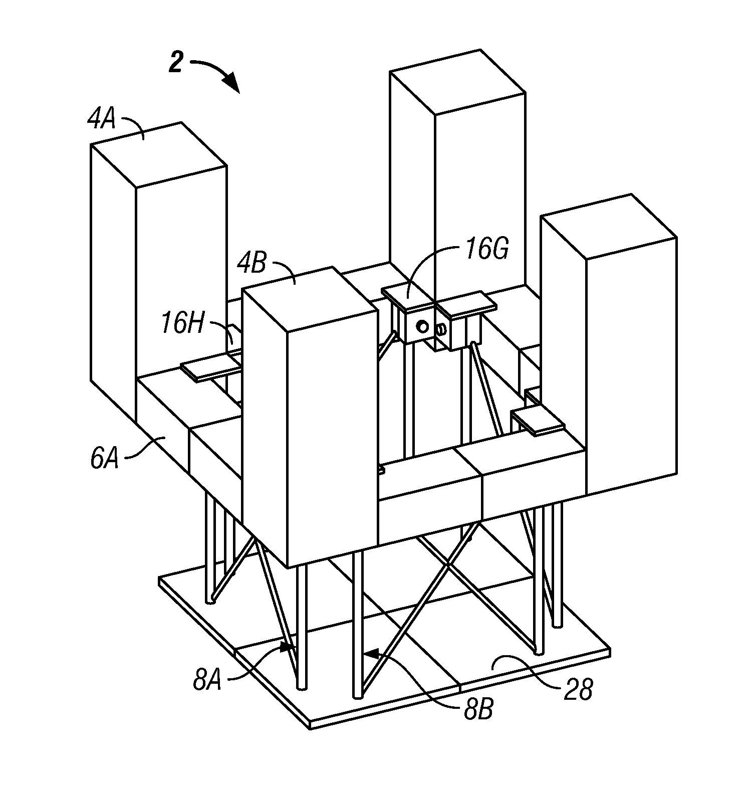
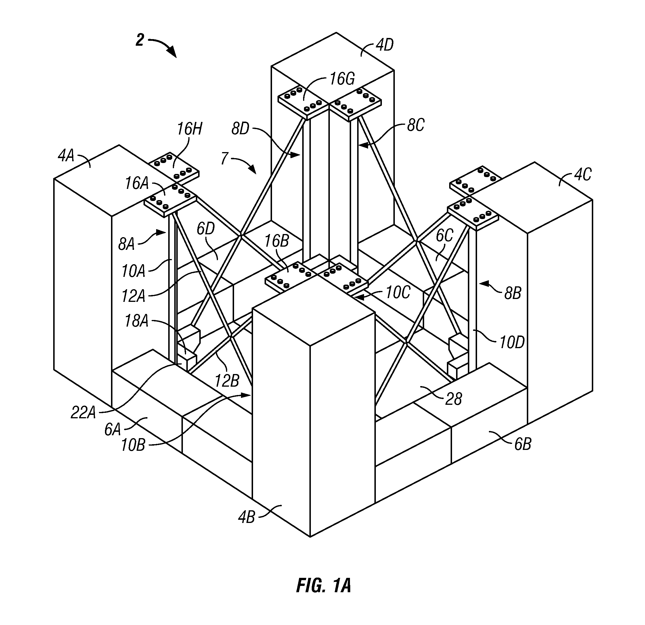
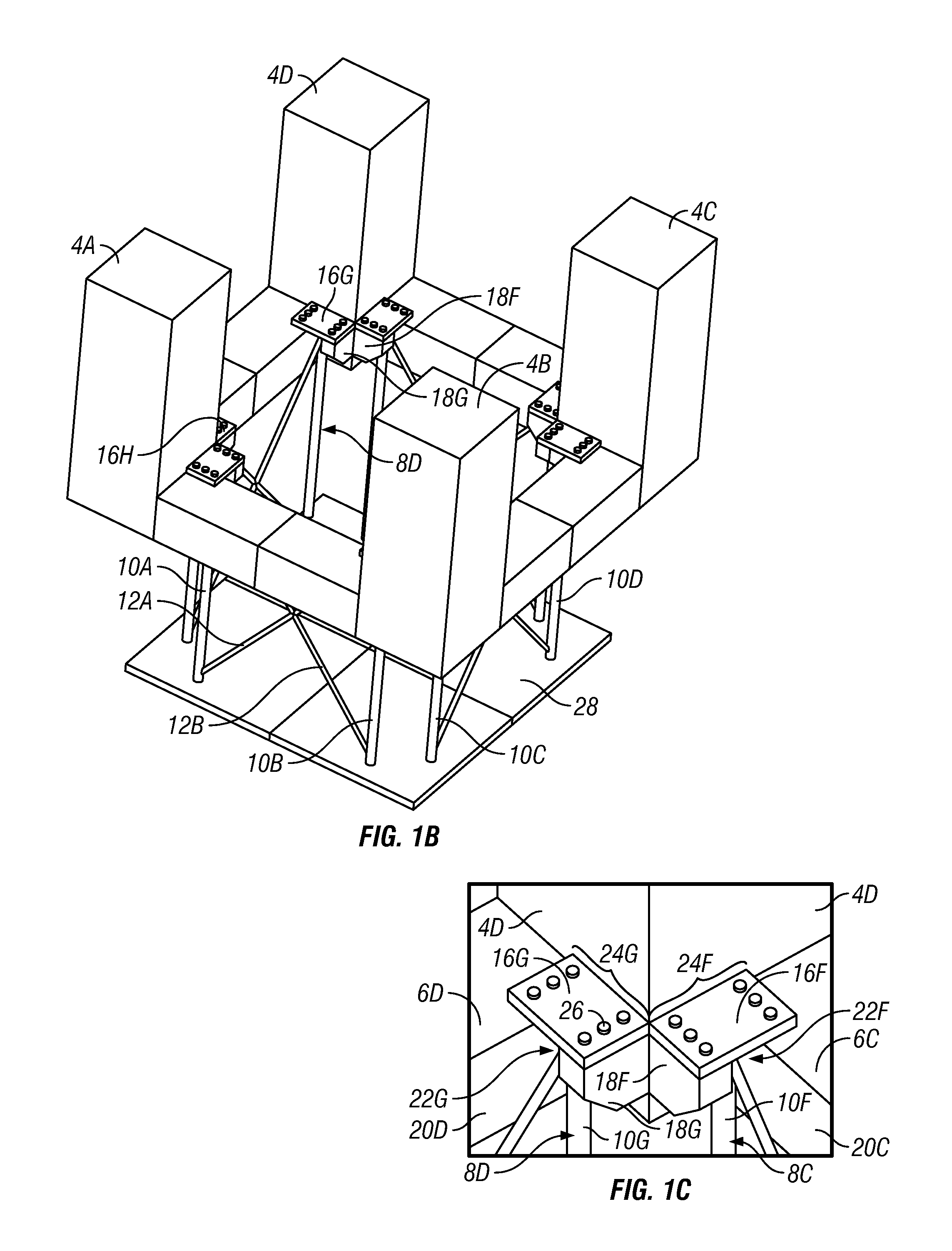
Truss heave plate system for offshore platform

a technology of offshore platforms and trusses, applied in special-purpose vessels, artificial islands, transportation and packaging, etc., can solve the problems of large topsides in both size and weight, large and expensive supporting offshore platforms, and initial limited depth

Inactive Publication Date: 2012-02-09
TECH FRANCE SA
View PDF35 Cites 18 Cited by
  • Summary
  • Abstract
  • Description
  • Claims
  • Application Information

AI Technical Summary

Benefits of technology

[0014]There remains a need for a different system and method for an offshore platform ha

Problems solved by technology

These reservoirs usually require large drilling rigs and variable payloads which result in very large topsides in both size and weight.
Large and expensive supporting offshore platforms are needed.
However, because the structure has a relatively large floating surface, one challenge is restricting movement caused by wave and wind action to provide a desired stability for operations.
However, the depth is initially limited, because the platform is built near or on shore at shallow depths.
While each of these systems offer solutions for a stabilized platform having a lowered heave plate, in practice the supporting structure for the heave plate to the platform may suffer from rigidity challenges.
Due to the extendable nature of the legs, no diagonal bracing between legs is shown that would be able to resist twisting and bending of the extended support struct

Method used


Image

  • Truss heave plate system for offshore platform
  • Truss heave plate system for offshore platform
  • Truss heave plate system for offshore platform

Examples


Embodiment Construction

[0028]The Figures described above and the written description of specific structures and functions below are not presented to limit the scope of what Applicant has invented or the scope of the appended claims. Rather, the Figures and written description are provided to teach any person skilled in the art how to make and use the inventions for which patent protection is sought. Those skilled in the art will appreciate that not all features of a commercial embodiment of the inventions are described or shown for the sake of clarity and understanding. Persons of skill in this art will also appreciate that the development of an actual commercial embodiment incorporating aspects of the present inventions will require numerous implementation-specific decisions to achieve the developer's ultimate goal for the commercial embodiment. Such implementation-specific decisions may include, and likely are not limited to, compliance with system-related, business-related, government-related and other...


PUM


Abstract

The disclosure provides an offshore platform and related method, having: a floating structure, a truss assembly coupled to the floating structure, and a heave plate coupled to the truss assembly. The floating structure includes a pontoon adapted to be disposed at least partially below a surface of water in which the offshore platform is disposed; and at least three vertically extending columns coupled to the pontoon, the columns having a larger lateral dimension than the pontoon coupled to the column, creating a pontoon offset portion. The truss assembly includes at least three separated walls of trusses slidably coupled to the columns, each truss wall having at least two vertically disposed truss legs, each truss leg being slidably coupled to a column at the pontoon offset portion independently from a truss leg of an adjacent wall; and cross-bracing between the truss legs of each of the truss walls.

Description

CROSS REFERENCE TO RELATED APPLICATIONS[0001]Not applicable.STATEMENT REGARDING FEDERALLY SPONSORED RESEARCH OR DEVELOPMENT[0002]Not applicable.REFERENCE TO APPENDIX[0003]Not applicable.BACKGROUND OF THE INVENTION[0004]1. Field of the Invention[0005]The disclosure relates generally to a system and method for offshore floating structures for use in the oilfield and related industries for exploration and extraction of minerals and resources from below surface waters. More specifically, the disclosure relates to a system and method for semi-submersible offshore platforms.[0006]2. Description of the Related Art[0007]With the significantly increasing demand on the oil and gas supply, offshore exploration and production from reservoirs has become vital to such supply. These reservoirs usually require large drilling rigs and variable payloads which result in very large topsides in both size and weight. Large and expensive supporting offshore platforms are needed. However, the expense of su...

Claims


Application Information

Patent Timeline
IPC IPC(8): E02B17/08E02B17/04
CPCB63B35/4413E02B2017/006E02B17/021E02B17/00B63B2039/067
Inventor XU, QI
Owner TECH FRANCE SA
Why Eureka
Try Eureka