Pulse simulator and a method for simulating pulse

a simulator and pulse technology, applied in the field of pulse simulator and improved method for simulating pulse, can solve the problems of not being able to fit in the simulator of a baby or child, not being able to accurately recognize and measure, and not being able to meet the needs of a modern pulse simulator device, etc., to achieve the effect of ensuring versatility in physical implementation, accurate recognition and measurement, and reducing/nulling known drawbacks

Inactive Publication Date: 2012-02-09
LAERDAL MEDICAL AS
View PDF6 Cites 12 Cited by
  • Summary
  • Abstract
  • Description
  • Claims
  • Application Information

AI Technical Summary

Benefits of technology

[0025]It is the principal object of the present invention to provide an improved device for simulating heart's pulse in a training apparatus such as a manikin, where pulse can be accurately recognized and measured by a student, for imparting a realistic medical training and which device ensures versatility in physical implementation and also substantially reduces / nullifies the known drawbacks of existing systems.

Problems solved by technology

Pneumatic Pulses:a. Uses a lot of air and is therefore not suitable for simulators with external compressor.b. Generates disturbing clicking noise from internal valve.c. Requires tubing running to each pulse site
Much too large to fit in baby or child simulators.
In all the pulse simulator devices, such as disclosed in U.S. Pat. No. 7,510,398 and DE 3301111, the need for a modern pulse simulator device, which works on a simple principle and simultaneously requires simple machinery and less energy for running, is not fully met.
Further, overcoming all the drawbacks as stated hereinbefore in existing systems have not been taught by such devices.
Further, such devices have the requirement of using a pump which not only consumes substantial energy which becomes a menace, particularly during battery operation, but also creates sound, prompting the student to feel the pulse, thus causing hindrance to his training by rendering the same unrealistic.
Further, the problem of generation of sound during its running and thereby rendering the training unrealistic is solved by this device.
This was particularly, having regard to the fact that the devices known in prior art for simulating pulses, were not fully focused on making the item subjected to pulsating movements as light as possible.

Method used


Image

  • Pulse simulator and a method for simulating pulse
  • Pulse simulator and a method for simulating pulse
  • Pulse simulator and a method for simulating pulse

Examples


Embodiment Construction

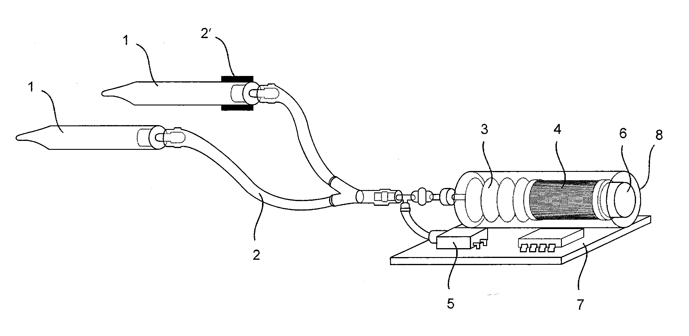
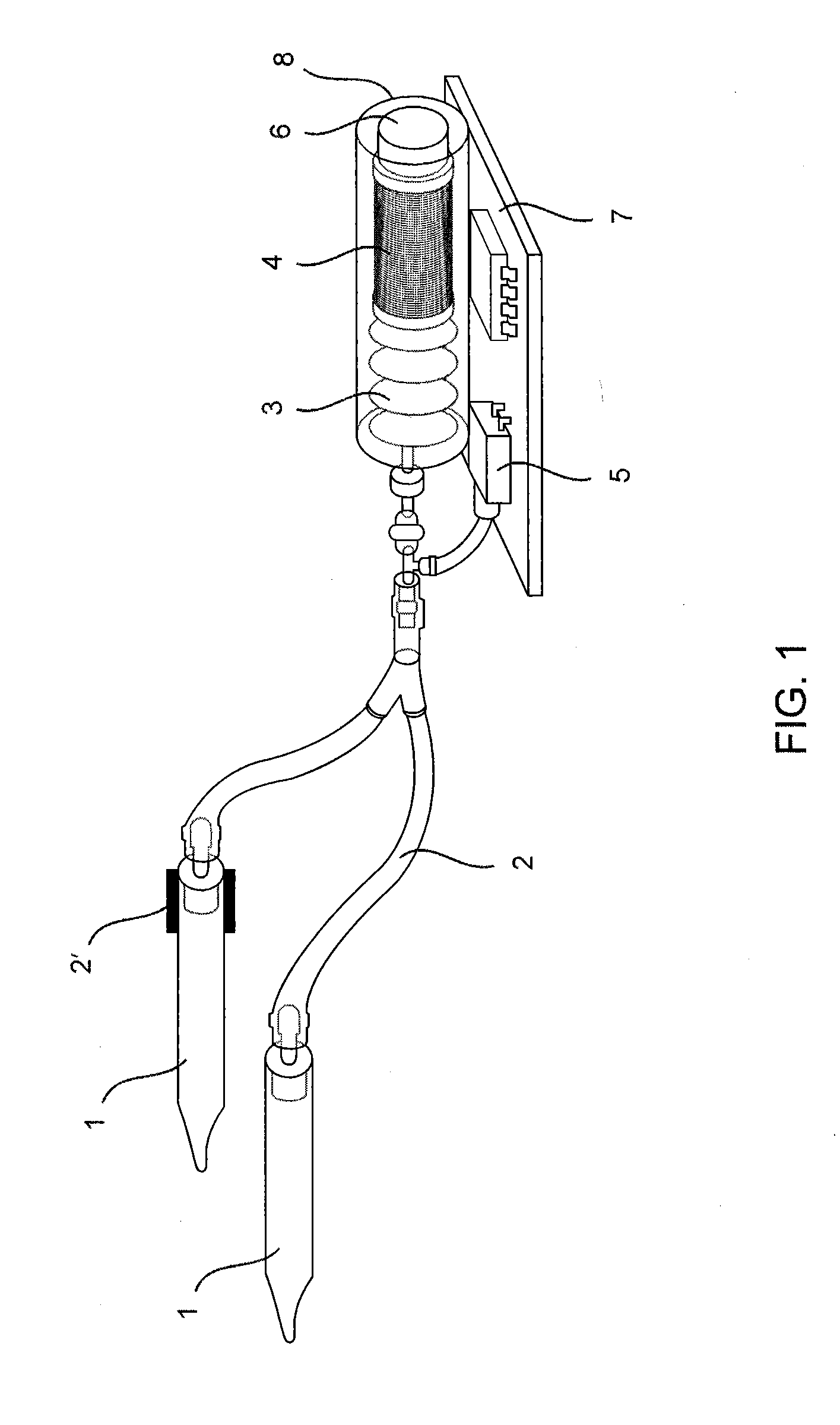
[0072]The accompanying FIG. 1 illustrates the lay-out of a preferred embodiment of the device for simulating heart's pulse according to the present invention. As can be seen, it basically comprises soft thin walled tubes 1 for pulse palpation connected with tubings 2 to flexible bellows 3. The tubes 2 are actually fluid lines, while the flexible bellows act as flexible pump means, as explained in the next paragraph. The flexible bellows are connected to a solenoid 4 that moves freely back and forth on a fixed magnetic core 6. The solenoid 4, flexible bellows 3 and fixed core 6, are preferably located within a housing 8 resting on a platform, having a printed circuit board (PCB) 7 mounted thereon. This is basically the complete system.

[0073]The tubing system is filled with a, preferably incompressible, fluid. When pulse palpation is performed, a small increased pressure in the fluid, due to the fact that a finger is pressed against one of the tubes 1, is detected by a pressure sensor...


PUM


Abstract

The present invention relates to an improved pulse simulator and to an improved method for simulating pulse. It comprises a palpation conveyor connected with a flexible pump means. The flexible pump is operatively coupled to a solenoid arranged about a fixed core. The solenoid is magnetized and demagnetized by an electrical energy source causing back and forth motion of the solenoid, with consequential expansion and contraction of the flexible pump means, thereby releasing fluid in back and forth direction to the palpation conveyor for generating pulse sensation.

Description

TECHNICAL FIELD[0001]The present invention in general, relates to an improved pulse simulator and to an improved method for simulating pulse. In particular, it relates to a device for simulating heart's pulse which has a simplified construction, requires less energy for its running and to a method for training medical students applying such device, which is user friendly, technically superior for creating real life pulse sensation and requires less energy. The present invention also ensures versatility in physical implementation.[0002]Preferably, the device is adapted for implementation in a medical training manikin.BACKGROUND ART[0003]With the increasing modernization in medical science, the need for sophisticated / accurate techniques and devices for training medical trainees has intensified. It is an established fact that feeling / sensing the heart's pulse is of immense importance in diagnosing the condition of the patient. A lack of or a weak pulse is a decisive factor to judge whe...

Claims


Application Information

Patent Timeline
Patent Type & Authority Applications(United States)
IPC IPC(8): G09B23/28
CPCG09B23/288G09B23/28
Inventor GOMO, OYSTEIN
Owner LAERDAL MEDICAL AS
Why Eureka
Try Eureka