Electrical plug-in connector and electrical plug-in connection

Inactive Publication Date: 2012-02-09
PHOENIX CONTACT GMBH & CO KG
View PDF9 Cites 32 Cited by
  • Summary
  • Abstract
  • Description
  • Claims
  • Application Information

AI Technical Summary

Benefits of technology

[0012]Therefore, the object of this invention is to develop the initially described electrical connector such that the mounting of the connector, especially the mounting of the contact elements in the contact carrier, is more easily poss

Problems solved by technology

If the number of contacts is increased, this leads—for otherwise uniform diameter of the connector—to more expensive mounting of the con

Method used


Image

  • Electrical plug-in connector and electrical plug-in connection
  • Electrical plug-in connector and electrical plug-in connection
  • Electrical plug-in connector and electrical plug-in connection

Examples


Embodiment Construction

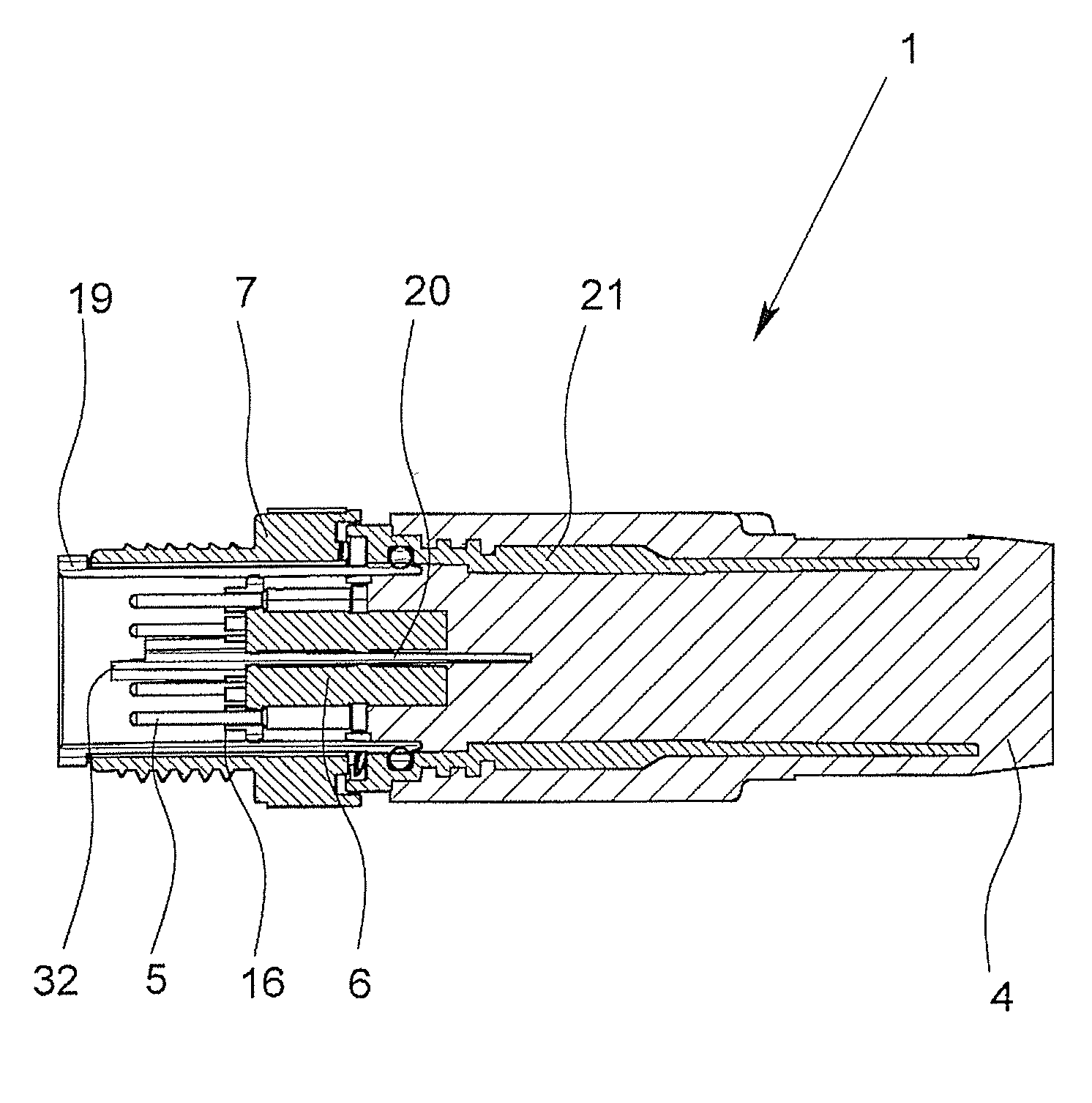
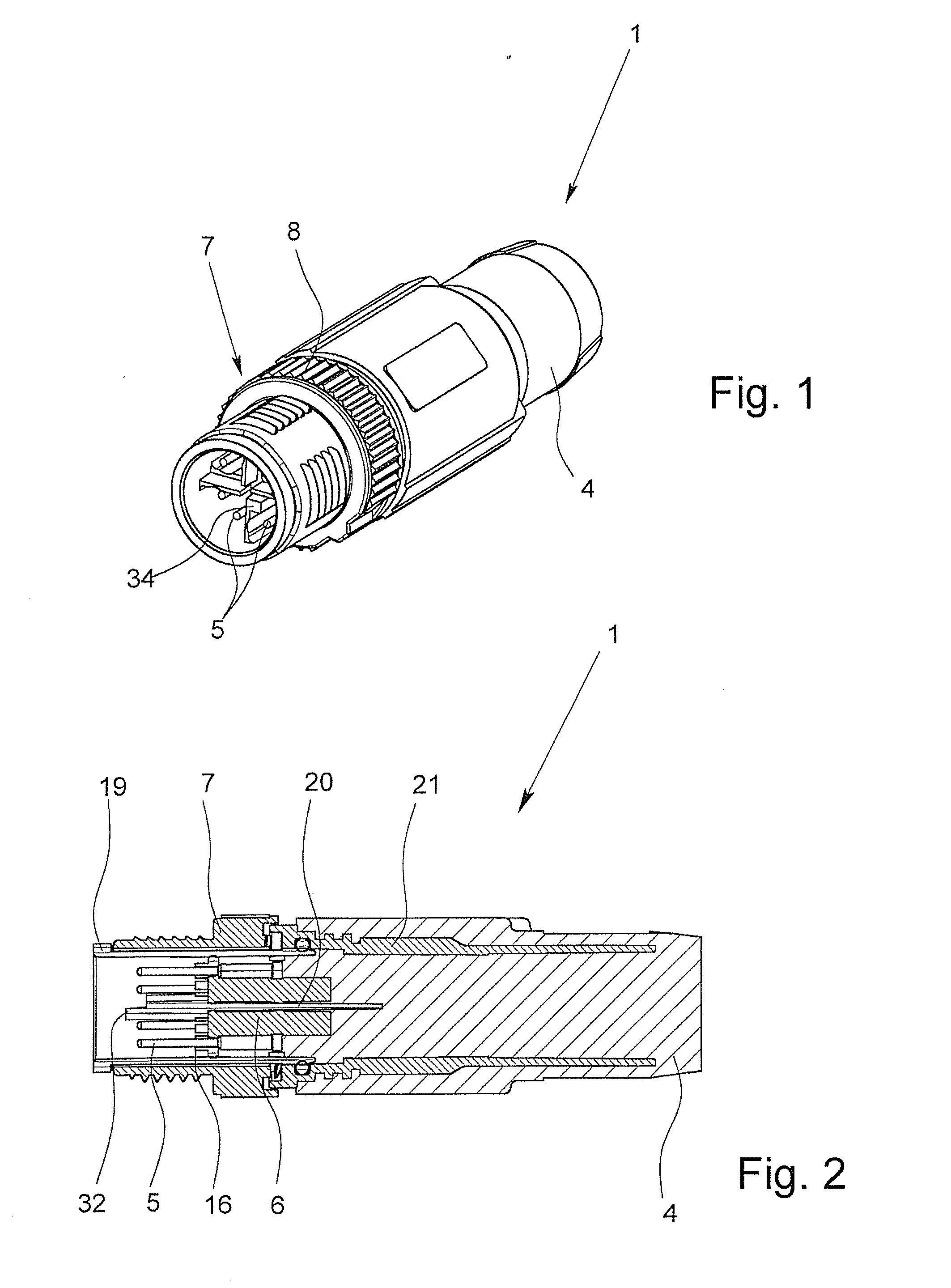
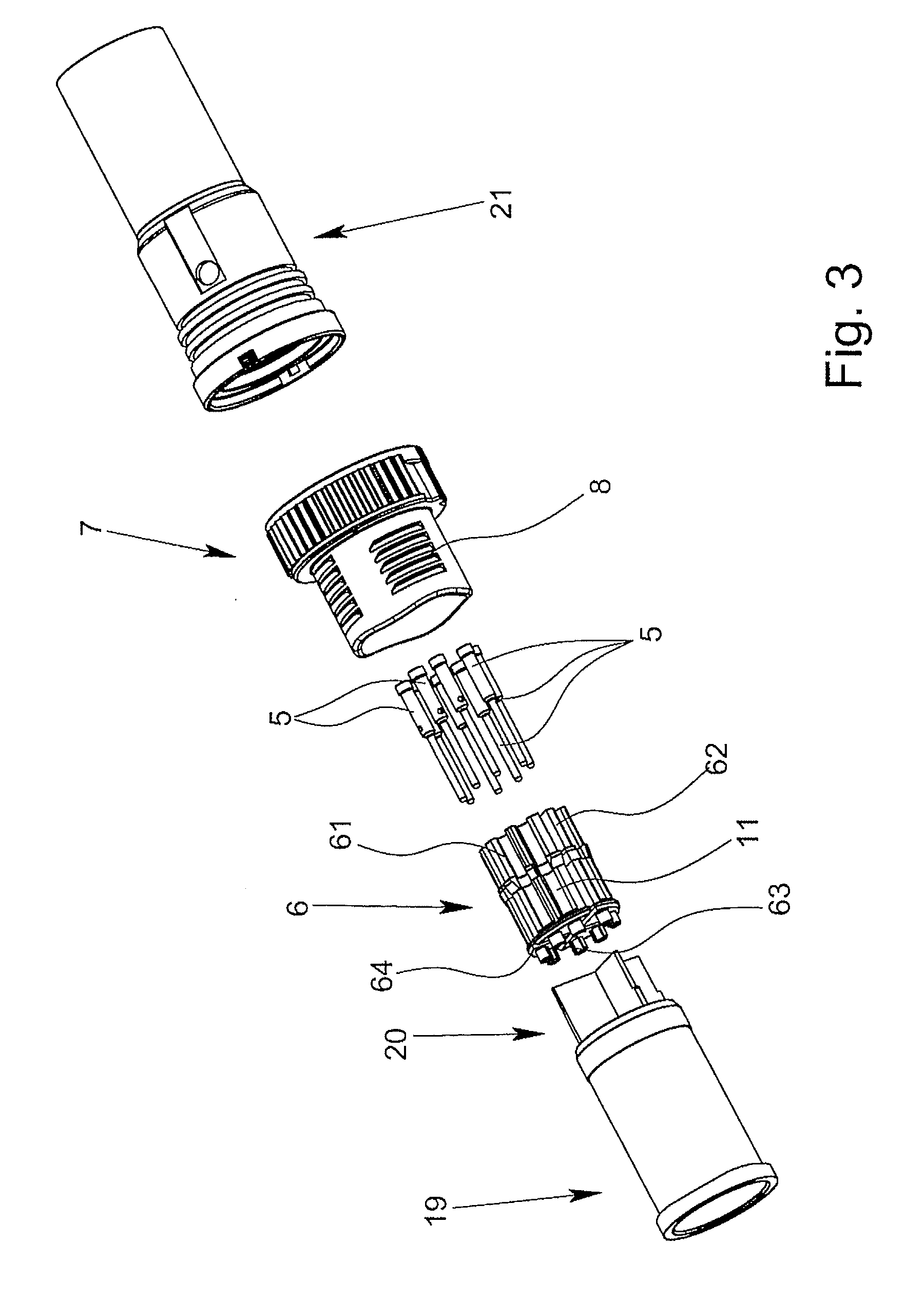
[0047]FIGS. 1 to 3 show an electrical connector 1 as part of an electrical plug-and-socket connection which is shown as a whole in FIGS. 8 & 9. The electrical connector 1 is used for detachable connection of a cable to a mating connector 2, which is shown in FIGS. 10 to 12. The electrical connector 1 has a grip body 4 which surrounds the cable and the cores 3 (shown in FIG. 4), a contact carrier 6 which holds and accommodates a total of eight contact elements 5, and a pivotally arranged union nut 7 with an external thread 8. The electrical connector 1 can be connected to the mating connector by threading the external thread 8 of the union nut 7 into the outer sleeve 9 of the mating connector 2 which has a corresponding inner thread 10.

[0048]As is apparent from FIGS. 1 and 10, both the external thread 8 of the union nut 7 and also the inner thread 10 of the outer sleeve 9 are interrupted in regions, i.e., both the external thread 8 and also the inner thread 10 have several unthreaded...


PUM

PropertyMeasurementUnit
Lengthaaaaaaaaaa
Electrical conductivityaaaaaaaaaa
Diameteraaaaaaaaaa

Abstract

An electrical connector for detachable connection of a multi-core cable to a mating connector with a grip body which surrounds the cable and the cable cores, a contact carrier which holds a plurality of contact elements and a pivotally arranged sleeve-shaped threaded part. The individual contact elements are connected electrically conductively to the individual cores and the sleeve-shaped threaded part can be screwed to a corresponding sleeve-shaped threaded part of the mating connector. The connector contact elements mounted in corresponding open grooves of the contact carrier which run parallel to its longitudinal axis, and a side of the contact carrier facing the mating connector, bordering the grooves, has through holes corresponding to the number of grooves, through which holes the ends of the contact elements that face away from the cores project in the longitudinal direction of the contact elements, being inserted obliquely and pivoted in to a parallel orientation.

Description

BACKGROUND OF THE INVENTION[0001]1. Field of the Invention[0002]The invention relates to an electrical connector for detachable connection of a multi-core cable to a mating connector, with a grip body which surrounds the cable and the cores of the cable, with a contact carrier which holds or accommodates a plurality of contact elements and with a pivotally arranged sleeve-shaped threaded part, the individual contact elements being connected electrically conductively to the individual cores and the sleeve-shaped threaded-part can be screwed to a corresponding sleeve-shaped threaded part of the mating connector.[0003]In addition, the invention relates to an electrical plug-and-socket connection to a connector and a mating connector, the connector having a union nut as the sleeve-shaped threaded part and the mating connector having an outer sleeve with an inner thread which corresponds to the external thread of the union nut of the connector and a mating contact carrier which holds or ...

Claims


Application Information

Patent Timeline
IPC IPC(8): H01R13/623H01R43/00H01R13/646
CPCH01R9/03H01R13/42Y10T29/49174H01R13/6471H01R13/6473H01R13/622
Inventor REIMCHEN, VALERI
Owner PHOENIX CONTACT GMBH & CO KG
Why Eureka
Try Eureka