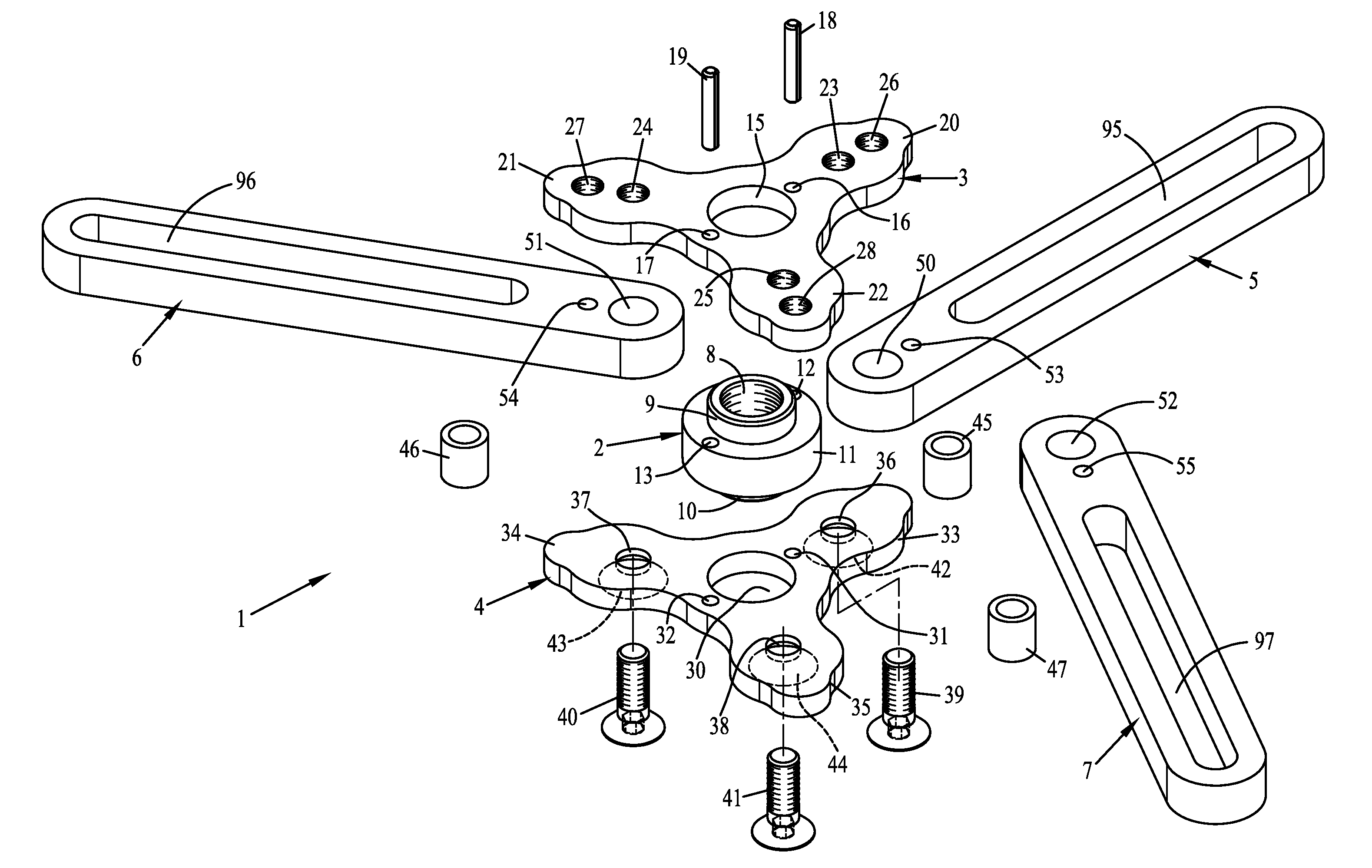
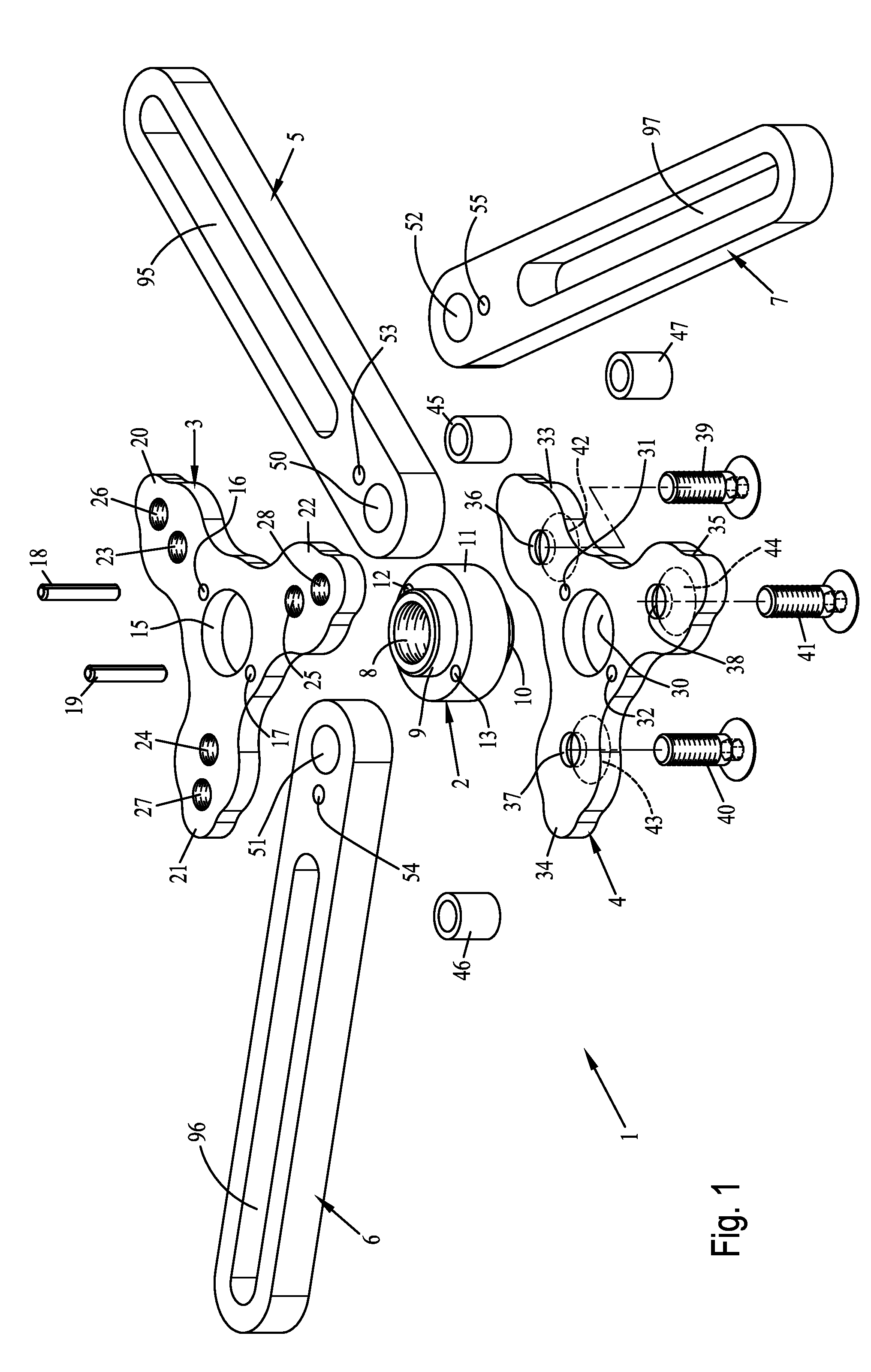
[0010]The design according to the present invention makes available a device that can be used variably for clutch housings of different shapes. In particular, the support device is designed for this purpose in a very special manner. Thus, this support device has, on the one hand, a central mounting element, into which the pressing device can be inserted. This support device is provided, furthermore, with a plurality of support arms, preferably three, which are each mounted pivotably at the mounting element of the support device. The support arms can thus be adjusted in terms of their angular positions in relation to one another at least approximately as desired, so that a concentric alignment of the pressing device with the transmission shaft of the double clutch transmission is possible in a simple manner and this is independent from the particular positioning of the passage holes or threaded holes of the clutch housing. The support arms can thus be aligned freely with these passage holes or threaded holes in a simple manner for different clutch housings with differently arranged passage holes and / or threaded holes. Tie bolts, which can be stationarily coupled, on the one hand, with the passage holes or threaded holes of the clutch housing and, on the other hand, adjustably mesh with the respective support arm, are provided according to the present invention for
coupling the support arms and hence the entire support device with these passage holes or threaded holes.
[0013]Furthermore, provisions may be made for the mounting element to have a central threaded
bushing, and for the pressing rod of the pressing device to be designed as a pressing screw and mounted axially adjustably in a central internal thread of the threaded
bushing, and for the threaded
bushing to have, in the horizontal alignment of the support arms, an upper mounting cylinder in its upper axial end area and a lower mounting cylinder in its lower axial end area, and for a bearing plate with a bearing bore to be mounted on the upper mounting cylinder, and for a support plate with a bearing bore to be mounted on the lower mounting cylinder, and for the threaded bushing to form, axially between its mounting cylinders, a radially expanded bearing
flange, at which the bearing plate is axially supported on the top side and at which the support plate is supported axially on the underside. This embodiment makes possible an extremely simple manufacture of the mounting element, especially for mounting the pressing device, which is preferably designed as a pressing screw, i.e., as a threaded spindle, and can correspondingly be screwed through the internal thread of the threaded bushing. Due to the special embodiment of the threaded bushing with the radially expanded bearing
flange thereof, the bearing plate and the support plate have a predefined distance from each other, so that the support arms can be pivotably mounted between these.
[0015]An extremely simple manufacturability and an extremely simple design of the mounting element are achieved, in particular, the mounting of the support arms is solved in an extremely simple manner, and an extremely high inherent stability is achieved due to the bearing tongues being arranged on both sides one on top of another in the axial direction for mounting one of the support arms each.
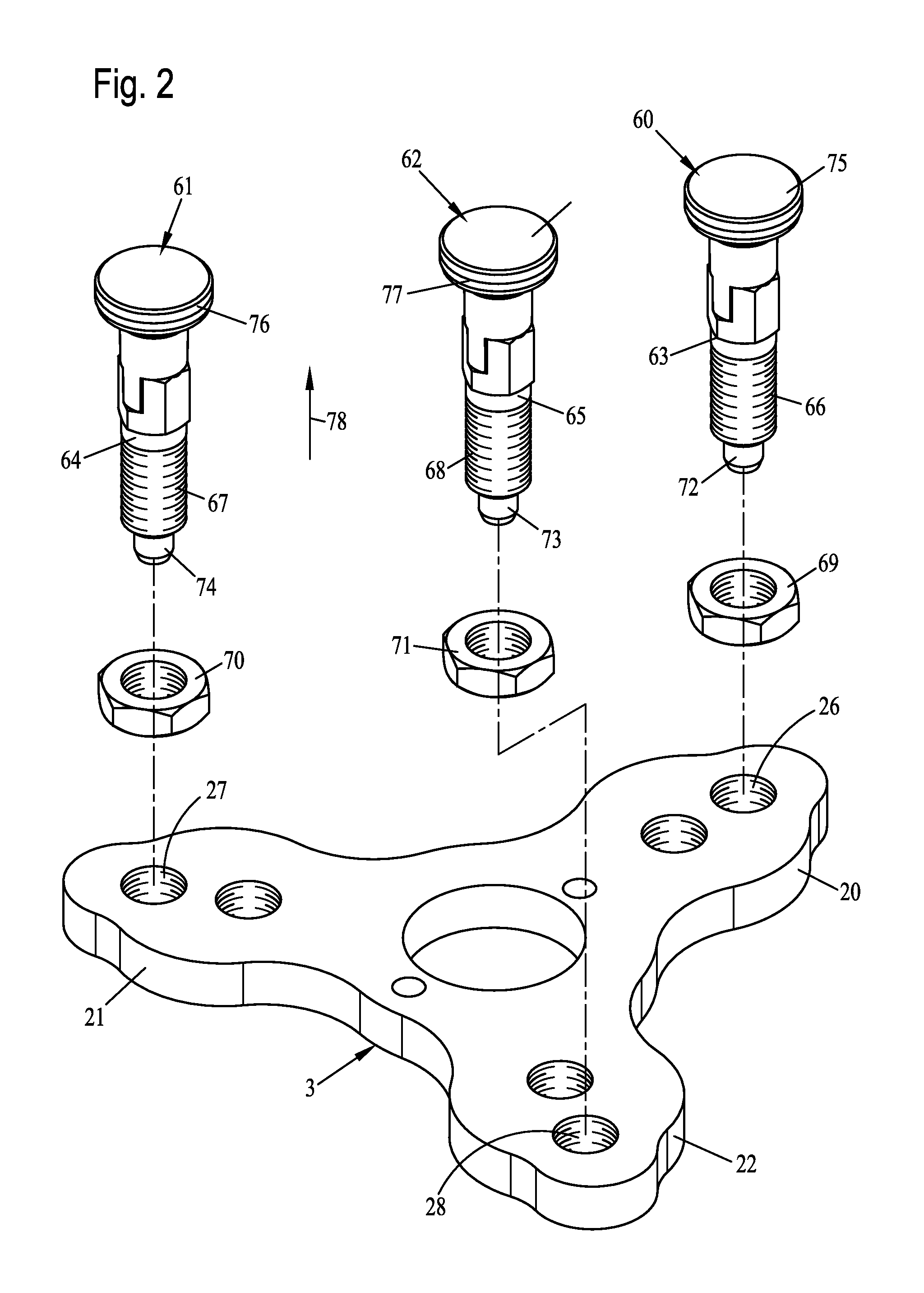
[0016]An extremely simple and
functional design of the locking pins, each associated with one of the support arms, is achieved due to the locking pins being of identical design and each having a guide element, with which elements the respective locking pin is screwed into a through thread of the bearing plate, and the respective guide element receiving, in an axially adjustable manner, a locking pin, which can be brought from a fixing position, in which it meshes axially with a fixing hole of the respective support arm, into a retracted
neutral position, in which it does not mesh with the fixing hole.
[0017]To release the locked position of the particular locking pin with its locking pin, provisions may, furthermore for the locking pin to have a tie rod, which is provided in its end area located axially opposite the locking pin with an external thread, with which the tie rod is screwed into an actuating element, and for the actuating element nonrotatably meshing with a locking web in a top-side
cross slot of the guide element in the locked position of the locking pin. Together with the locking pin, this actuating element can be retracted in the axial direction against a
spring force, so that the “locking” meshing of the locking pin with the corresponding support arm is abolished and this pin can be pivoted approximately as desired.

