
Push-to-insert, push-to-eject and pull-to_extract card connector

a technology of push-to-eject, push-to-eject and pull-to-extract, which is applied in the direction of coupling device connections, instruments, conveying record carriers, etc., can solve the problems of imposing limitations on the size of the connector plug, the inability or impracticality of using many conventional mechanical structures, and the inability to use many conventional mechanical structures

Inactive Publication Date: 2012-02-16
GOOGLE LLC
View PDF1 Cites 1 Cited by
  • Summary
  • Abstract
  • Description
  • Claims
  • Application Information

AI Technical Summary

Benefits of technology

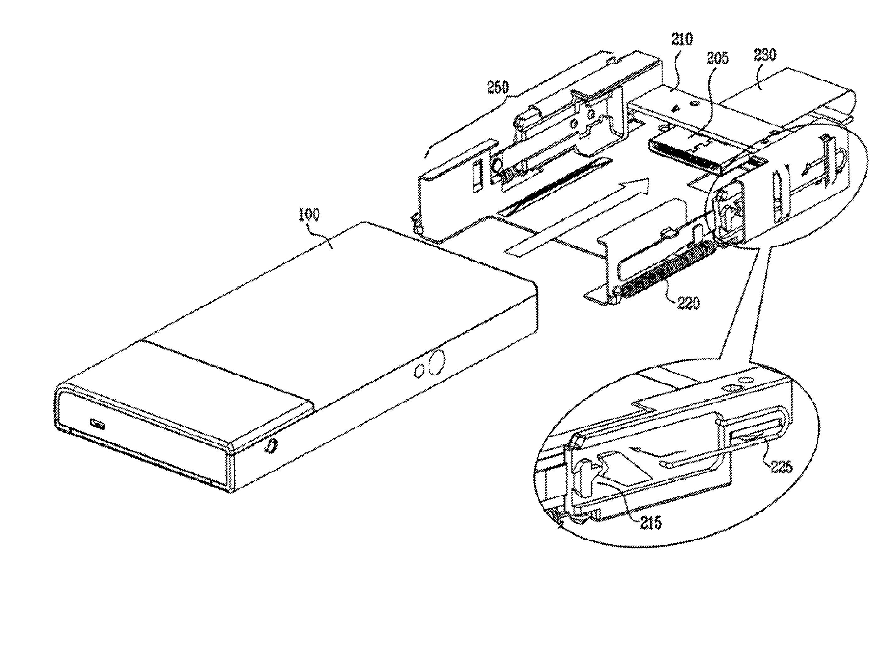
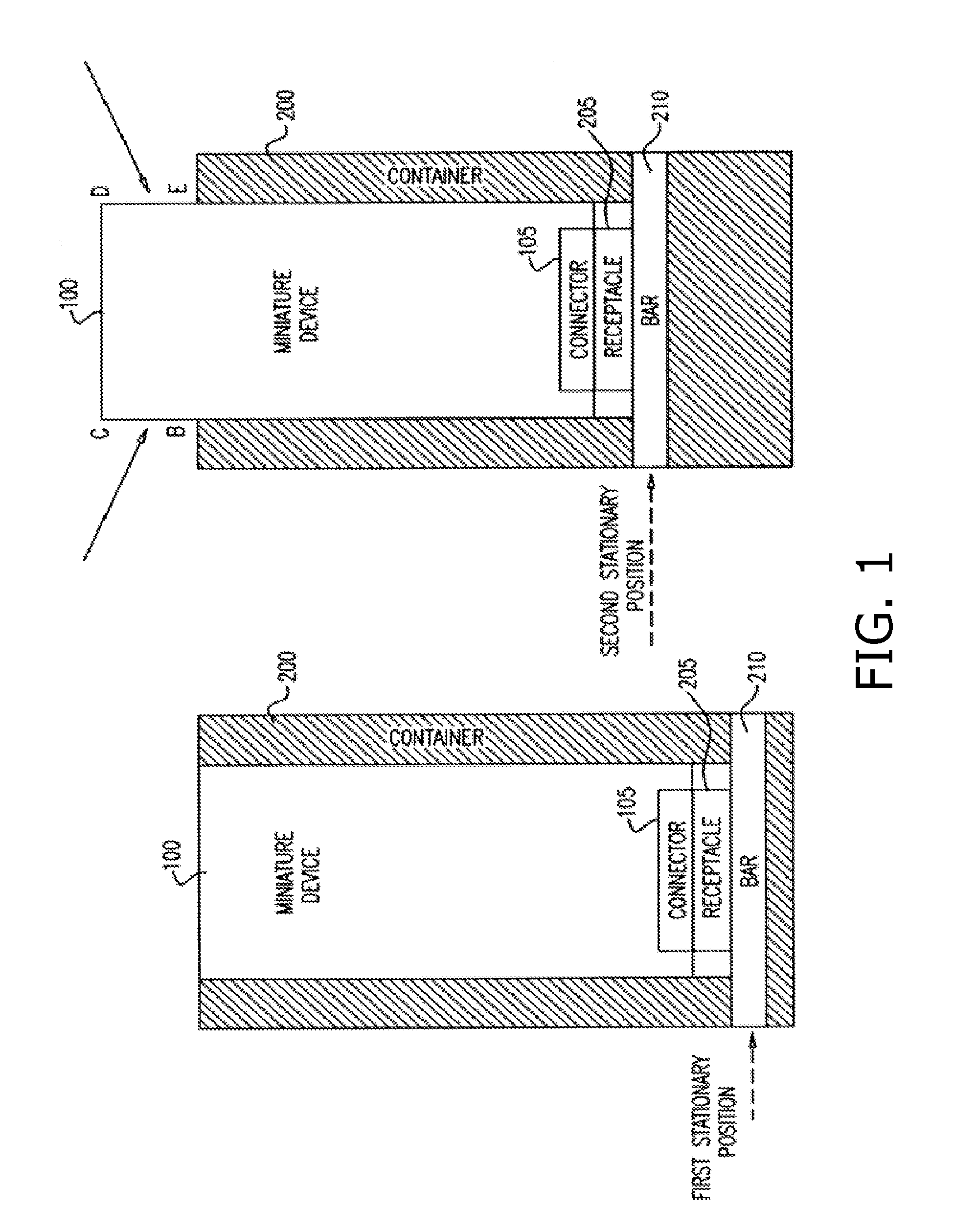
[0010]Embodiments of the present invention overcome the need for slack length on a connector plug by introducing a moveable receptacle for the connector plug. Whereas conventional receptacles are rigidly fixed to their chassis, the moveable receptacle slides, or “floats” in its chassis. The moveable receptacle has mechanical parts including a locking system, a flexible PCB, and a retractable mechanism. The moveable receptacle is designed so as to have two stationary positions. After the receptacle is pushed for inserting a connector plug therein, the receptacle locks into a first stationary position. After the receptacle is pushed to extract the connector plug therefrom, the receptacle rests in a second stationary position. The connector plug is still attached to and in electrical contact with the receptacle when the receptacle is in the rest position; however, the device housing the connector plug protrudes sufficiently so that a person can grasp the device and pull it out, thereby disengaging the connector plug from the pins of the receptacle. Such a “push-to-insert, push-to-eject and pull-to-extract” mechanism enables use of shorter connector plugs, by avoiding the need for slack space on the connector plug side, and requiring slack space only for movement of the receptacle.

Problems solved by technology

When attempts are made to reduce electronic devices to miniature sizes, the small available space makes it impossible or impractical to use many of the conventional mechanical structures.
Thus challenges arise in finding alternative structures that require less space.
Conventional receptacles use insert and eject mechanisms that require slack space for pushing a connector plug into a receptacle beyond its locked position, and thus impose limitations on how small a connector plug may be.

Method used


Image

  • Push-to-insert, push-to-eject and pull-to_extract card connector
  • Push-to-insert, push-to-eject and pull-to_extract card connector
  • Push-to-insert, push-to-eject and pull-to_extract card connector

Examples


Embodiment Construction

[0033]Embodiments of the present invention relate to a miniature electrical connector plug for an electronic device, and a receptacle therefor. A miniature electrical connector plug is set into a surface of an electronic device, and a receptacle is mounted into a container chassis. Due to its small size, the miniature connector plug may not have the necessary slack length for use with a conventional push-push insert / eject mechanism, whereby the connector plug must be pushed into the chassis beyond its locked engaged position in order to fully disengage the connector plug with pins in the receptacle.

[0034]To overcome this limitation, embodiments of the present invention introduce a receptacle mounted on a slideable bar that has two stationary positions. The first stationary position, a locked position, is attained after the electronic device is pushed into the housing of the receptacle for insertion of the connector plug into the receptacle. The second stationary position, a rest pos...


PUM


Abstract

An apparatus, including a chassis having an opening into which an electrical component is insertable, means for coupling to the electrical component, the means for coupling slidably movable, relative to the chassis, in a first direction generally away from the opening, and in a second direction generally toward the opening to a first position in response to force in the first direction exerted upon the means for coupling, and to a second position in response to force in the first direction exerted upon the means for coupling when the means for coupling is in the first position, wherein the first position is different, with respect to the chassis, than the second position.

Description

PRIORITY REFERENCE TO RELATED APPLICATIONS[0001]This application claims benefit of U.S. Provisional Application No. 61 / 060,522, entitled PUSH-TO-INSERT, PUSH-TO-EJECT AND PULL-TO-EXTRACT CARD CONNECTOR, filed on Jun. 11, 2008 by inventors Eyal Bychkov, Yaniv Maydar, Noam Bernstein and Itay Cohen.FIELD OF THE INVENTION[0002]The field of the present invention is connectors for electronic devices.BACKGROUND OF THE INVENTION[0003]The feats of miniaturization are astounding. Given Imaging, Ltd. of Yoqneam, Israel, manufactures a miniature 11 mm×26 mm video camera that fits inside a pill that is swallowed by a patient. SanDisk Corporation of Milpitas, Calif., manufactures a 16 GB MicroSDHC card having physical dimensions 15 mm×11 mm×0.7 mm, which is the size of a fingernail. Western Digital Corporation of Lake Forest, Calif. now manufactures a 320 GB portable hard drive having physical dimensions 126 mm×79 mm×15 mm, which is the size of a passport, and weighs 180 g. Three of these passpor...

Claims


Application Information

Patent Timeline
Patent Type & Authority Applications(United States)
IPC IPC(8): H01R13/629
CPCG06K13/0806H01R23/10H01R13/635H01R13/6275
Inventor BYCHKOV, EYALMAYDAR, YANIVBERNSTEIN, NOAMCOHEN, ITAY
Owner GOOGLE LLC
Learn More