
Slide Pen

Inactive Publication Date: 2008-01-03
MORRIS CORP
View PDF11 Cites 0 Cited by
  • Summary
  • Abstract
  • Description
  • Claims
  • Application Information

AI Technical Summary

Benefits of technology

[0013]Accordingly, the present invention has been made keeping in mind the above problems occurring in the prior art, and an object of the present invention is to provide a slide pen having a pen core, a pen core slider holding and coupling the pen core, and a body casing holding the pen core slider, wherein the pen core is moved in and out by sliding the pen core slider, with the goal of providing a writing implement having a simple structure and easy assembly.
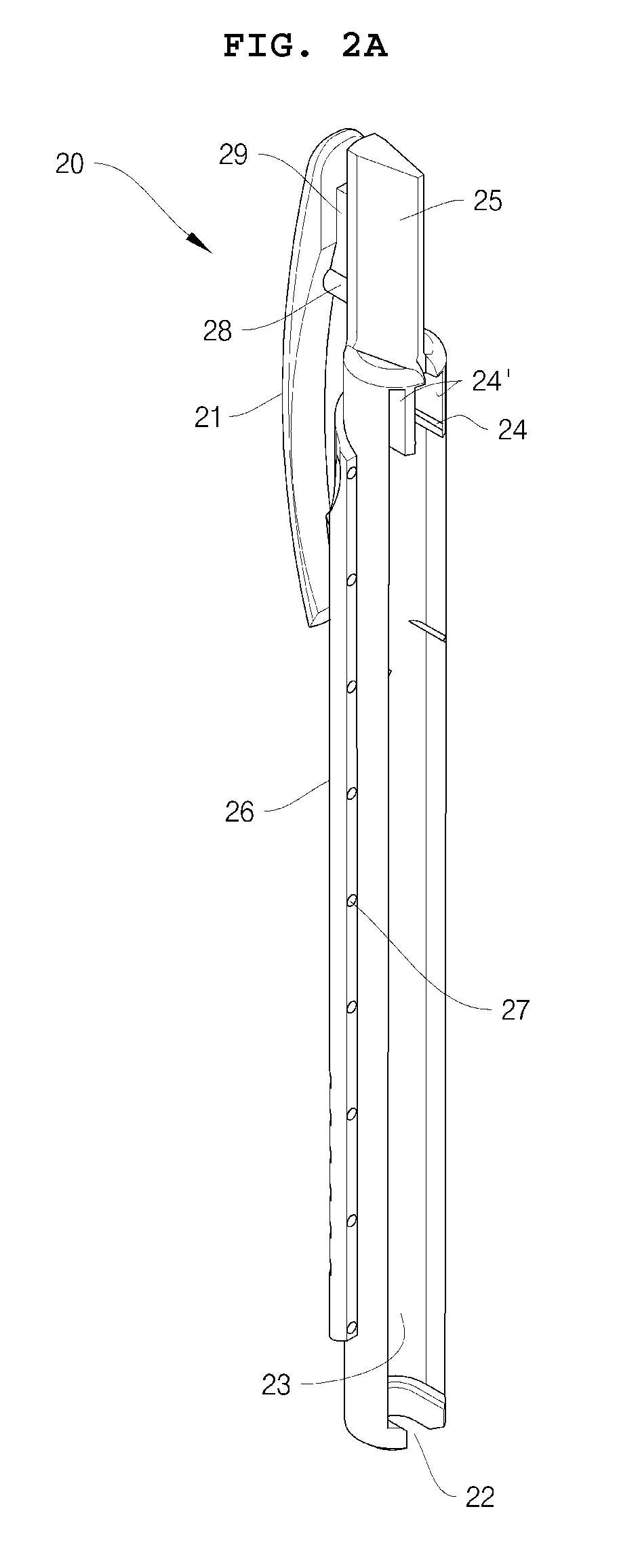
[0016]Here, the guide slot of the upper portion of the body casing may communicate with one end of the intermediate portion of the body casing, because the guide ridges of the pen core slider are adapted to pass through the guide slot when the pen core slider coupled with the pen core is inserted into the body casing, and thereby the pen core slider coupled with the pen core can be assembled to the body casing.
[0021]Most preferably, the length of the sheath may be shorter than that of the open intermediate portion of the body casing, and the movement distance of the sheath may be equal to the distance that the guide ridges of the pen core slider move in the guide slot of the body casing. Thereby, the pen core slider smoothly slides and the nib of the pen core can protrude sufficiently.

Problems solved by technology

However, most of these lock-type writing implements include four or five constituent pieces, such as the pen core case, the operating button, the upper and lower cases, and so on, that is, they have many parts and a complicated structure, so that the production cost thereof is high, and assembly is difficult.

Method used


Image

  • Slide Pen
  • Slide Pen
  • Slide Pen

Examples


Embodiment Construction

[0033]Reference will now be made in greater detail to a preferred embodiment of the invention, an example of which is illustrated in the accompanying drawings. Wherever possible, the same reference numerals will be used throughout the drawings and the description to refer to the same or like parts.

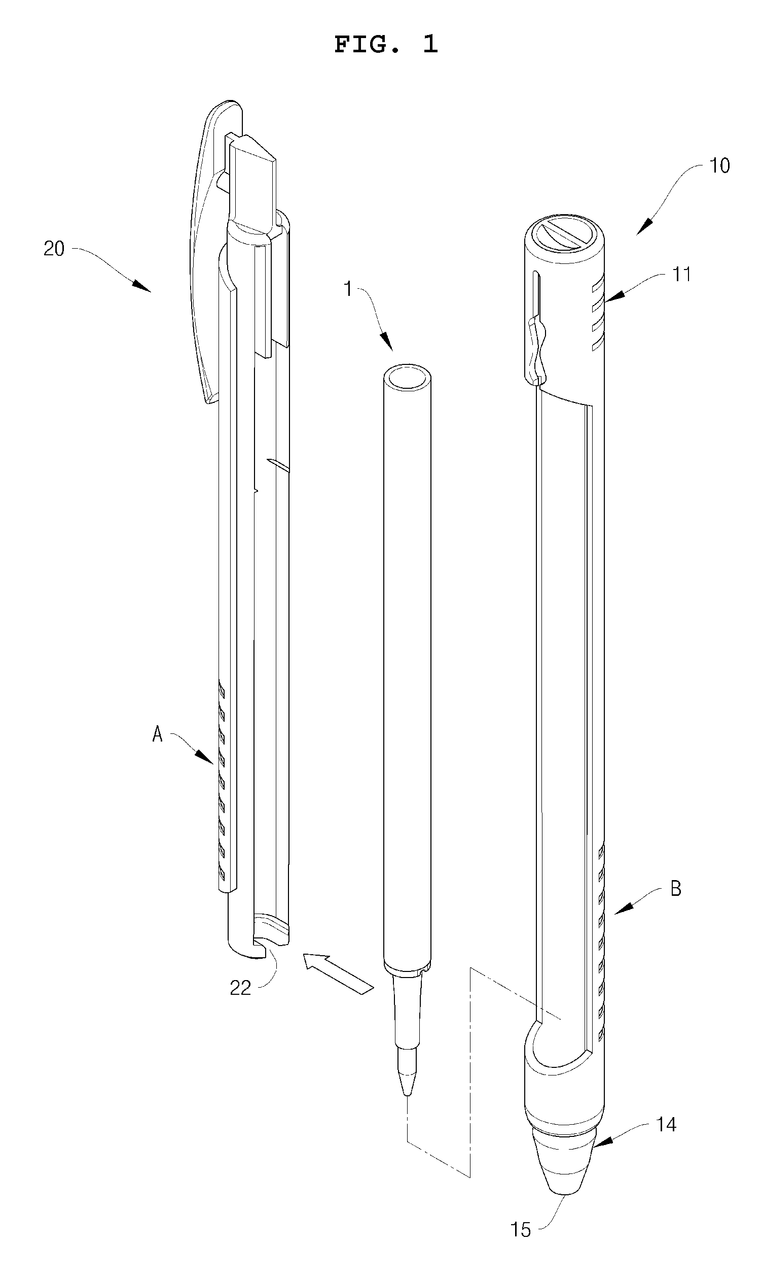
[0034]FIG. 1 is an exploded perspective view illustrating a slide pen according to an embodiment of the present invention.

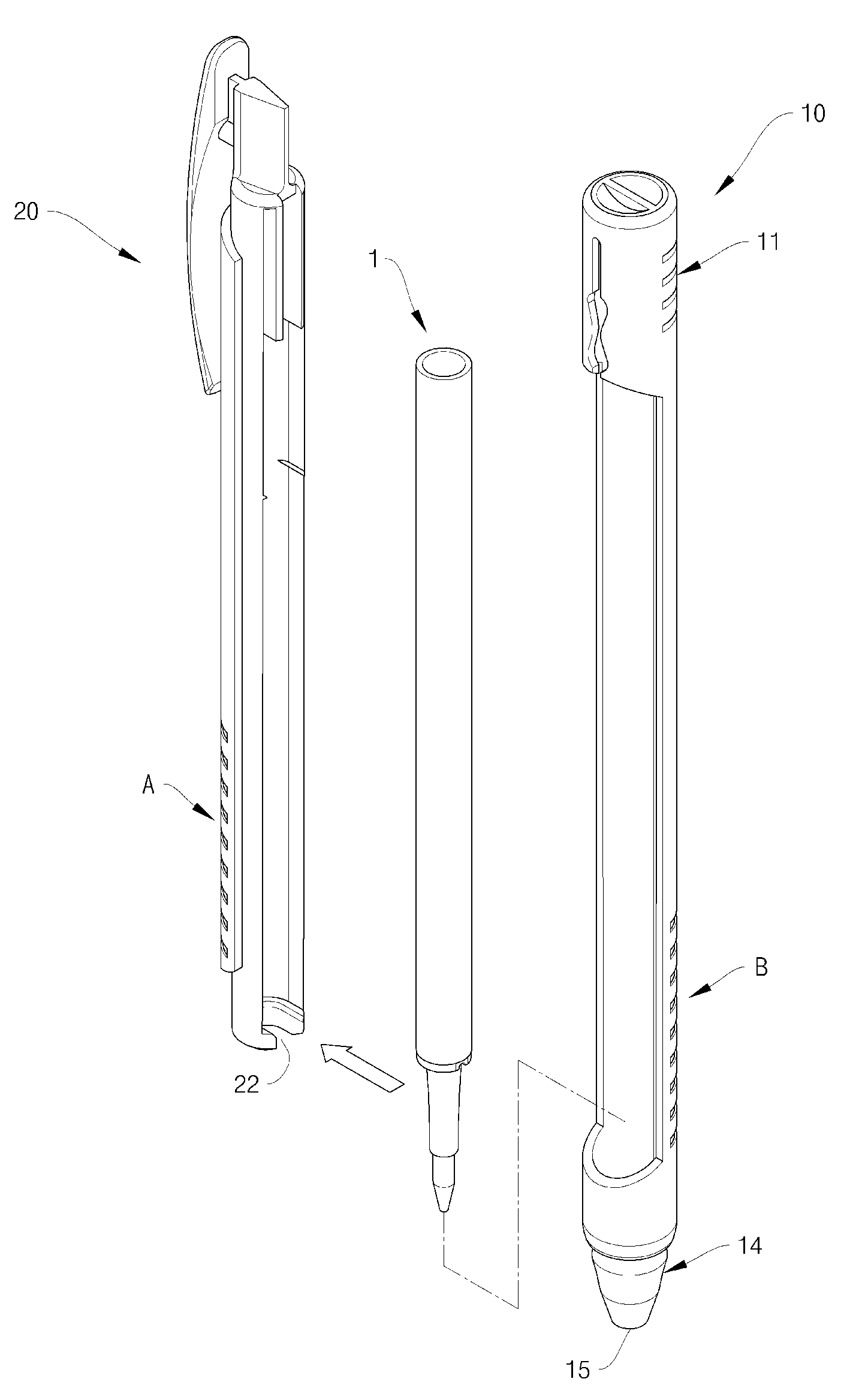
[0035]As illustrated in FIG. 1, the slide pen is comprised of a pen core 1, a pen core slider 20 holding the pen core 1 and removably coupled with the pen core, and a body casing 10 removably holding the pen core slider 20.

[0036]The body casing 10 has an intermediate portion that is partially open. Similarly, the pen core slider 20 is partially open in a longitudinal direction. The pen core 1 is coupled to the pen core slider 20, and then the pen core slider 20 having the pen core 1 is assembled into the body casing 10. As a result, the slide pen of the present inventio...


PUM


Abstract

Disclosed is a slide pen. The slide pen includes (a) a pen core having a nib, (b) a tubular pen core slider having an open lower end, a pen core coupler, and guide ridges formed at an upper portion thereof, so as to allow the nib of the pen core to protrude through the lower end thereof and to allow the pen core to be held and coupled therein, and (c) a body casing having a tubular upper portion formed with a guide slot so as to allow the guide ridges of the pen core slider to vertically move and be fixed, a tubular intermediate portion being partially open such that the pen core slider is held inside so as to allow the outer circumference of the pen core slider to be exposed outside, and a conical lower portion having an open lower end so as to allow the nib of the pen core to be moved in and out. Thereby, when the guide ridges of the pen core slider vertically move in the guide slot of the upper portion of the body casing, the pen core slider slides in the body casing, and the nib of the pen core coupled to the pen core coupler of the pen core slider comes in and out through the lower end of the body casing.

Description

CROSS-REFERENCE TO RELATED APPLICATIONS[0001]This application claims priority to Korean application no. 10-2006-0060460, filed Jun. 30, 2006, which is hereby incorporated by reference for all purposes.BACKGROUND OF THE INVENTION[0002]1. Field of the Invention[0003]The present invention relates, in general, to a slide pen having a pen core, a pen core slider, and a body casing, in which the pen core is moved in and out by means of the movement of a pen core slider coupled with a pen core held in the body casing.[0004]2. Description of the Prior Art[0005]In general, a writing implement comprises a pen core and spring, a pen core case, an operating button, and upper and lower cases.[0006]In order to use the writing implement having this operating button, the operating button, located at an upper portion of the writing implement, is pressed to protrude the pen core. When use of the writing implement is complete, the operating button is again pressed to retract the pen core. Thereby, the...

Claims


Application Information

Patent Timeline
IPC IPC(8): B43K5/16
CPCB43K24/04B43K23/008B43K3/04B43K25/02
Inventor YOON, HYUN-SON
Owner MORRIS CORP
Learn More