Control device for stirling engine

Inactive Publication Date: 2012-02-23
TOYOTA JIDOSHA KK
View PDF5 Cites 2 Cited by
  • Summary
  • Abstract
  • Description
  • Claims
  • Application Information

AI Technical Summary

Benefits of technology

[0010]According to the foregoing aspects of the invention, it is possible to prevent or restrain a torque fluctuation gre

Problems solved by technology

Consequently, it is considered that this technology may sometimes bring about o

Method used


Image

  • Control device for stirling engine
  • Control device for stirling engine
  • Control device for stirling engine

Examples


Embodiment Construction

[0018]Hereinafter, embodiments of the invention will be described in detail with reference to the drawings.

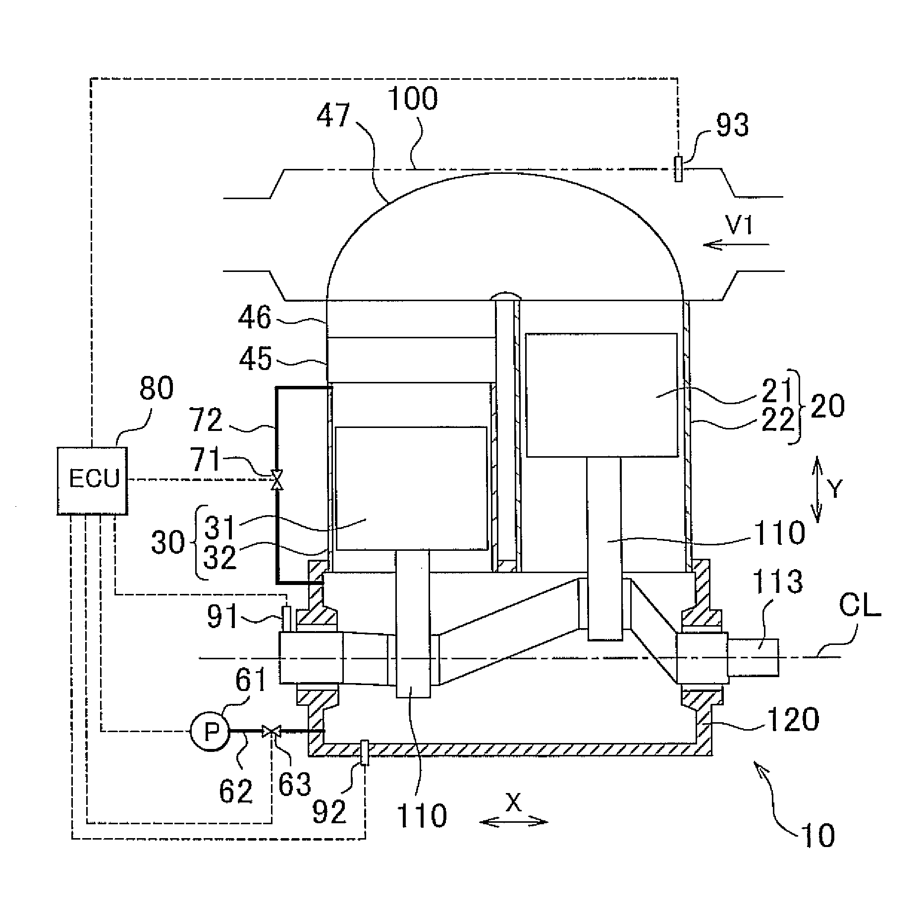
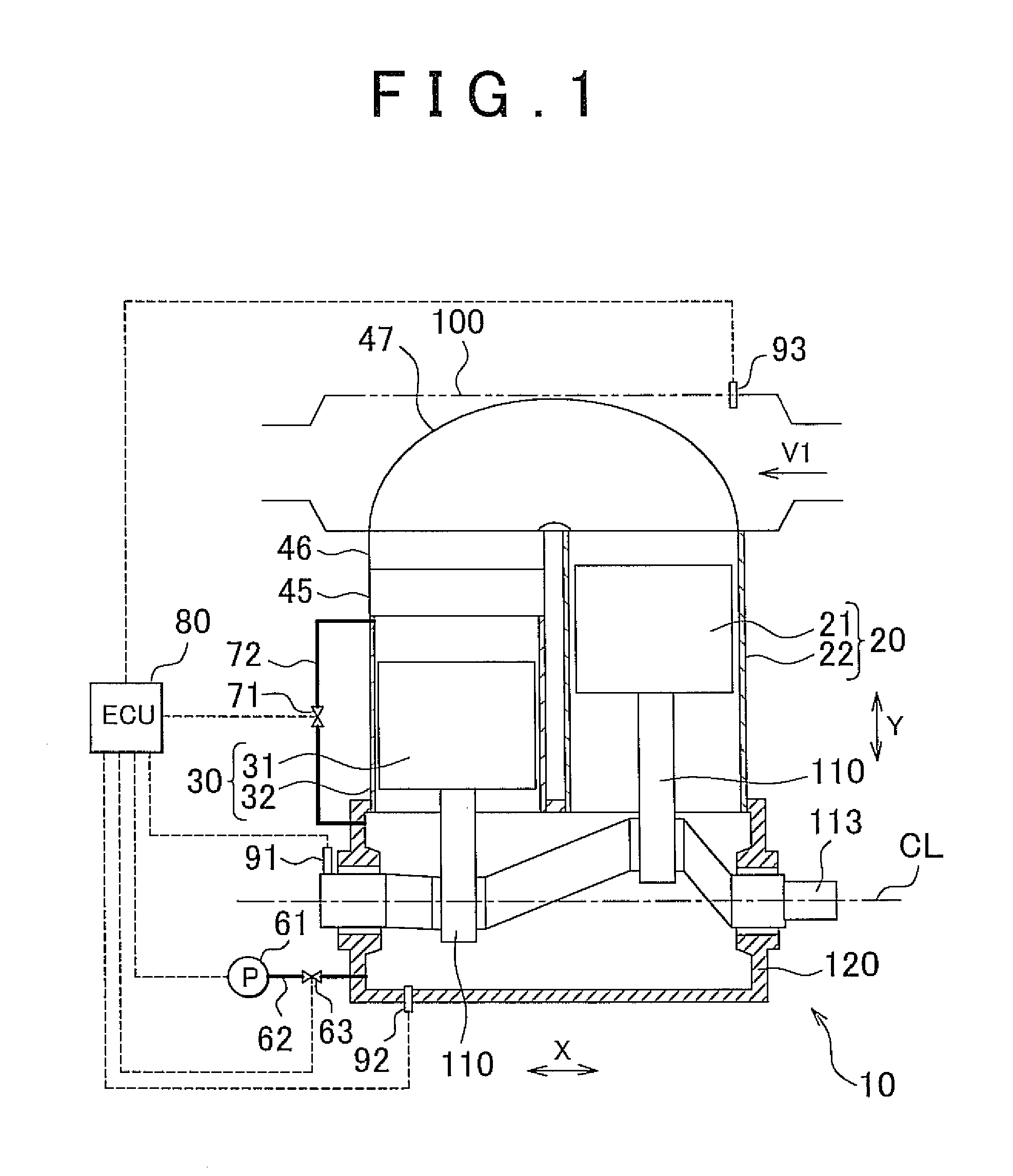
[0019]FIG. 1 is a diagram showing an ECU 80, which serve as the control device for a Stirling engine in accordance with an embodiment of the invention, together with a Stirling engine 10. The Stirling engine 10 is a two-cylinder α-type Stirling engine. The Stirling engine 10 includes a pair of cylinder units, specifically, a high-temperature cylinder unit 20 and a low-temperature cylinder unit 30, which are disposed in an in-line parallel arrangement such that a cylinder arrangement direction X of the cylinders is parallel to an extending direction of a crankshaft line CL. The high-temperature cylinder unit 20 has an expansion piston 21 that serves as a high-temperature piston, and a high-temperature cylinder 22. The low-temperature cylinder unit 30 has a compression piston 31 that serves as a low-temperature piston, and a low-temperature cylinder 32. The reciprocating phase of...


PUM


Abstract

A control device for a Stirling engine including: two cylinder units; and a decompression portion that brings about a decompression effect of reducing a degree of compression of a working fluid that flows back and forth between the two cylinder units, by letting out the working fluid that flow back and forth between the two cylinder units, when the Stirling engine is started; the control device including a control portion that controls the decompression portion so that the decompression effect is gradually weakened after the Stirling engine is started.

Description

CROSS-REFERENCE TO RELATED APPLICATIONS[0001]This application claims priority to Japanese Patent Application No. 2010-185605 filed on Aug. 20, 2010, which is incorporated herein by reference in its entirety including the specification, drawings and abstract.BACKGROUND OF THE INVENTION[0002]1. Field of the Invention[0003]The invention relates to a control device for a Stirling engine and, more particularly, to a Stirling engine control device that is provided for a Stirling engine constructed so as to obtain a decompression effect of reducing the degree of compression of the working fluid.[0004]2. Description of Related Art[0005]In recent years, Stirling engines are drawing attention as a measure to recover exhaust heat from an internal combustion engine mounted in a vehicle, such as a passenger car, a bus, a truck, etc., or exhaust heat from a factory. The Stirling engine can be expected to achieve high heat efficiency. Furthermore, since the Stirling engine is an external combustio...

Claims


Application Information

Patent Timeline
IPC IPC(8): F02G1/04
CPCF02G1/05
Inventor KATAYAMA, MASAAKISAWADA, DAISAKUYAGUCHI, HIROSHI
Owner TOYOTA JIDOSHA KK
Why Eureka
Try Eureka