Hybrid electrical power source combining stirling engine driven alternator with supplementing electrical energy storage

a technology of hybrid power supply and alternator, which is applied in the direction of electric generator control, machines/engines, transportation and packaging, etc., can solve the problems of reducing output voltage, limiting the power supplied to the user load, and limiting the application of the power supply system

Inactive Publication Date: 2009-08-20
SUNPOWER
View PDF6 Cites 27 Cited by
  • Summary
  • Abstract
  • Description
  • Claims
  • Application Information

AI Technical Summary

Benefits of technology

[0015]An electrical power source has a free-piston Stirling engine driving an alternator and has a battery. A Stirling engine / alternator controller modulates the piston stroke between a maximum and a minimum stroke to maintain the bus voltage at a design nominal bus voltage (V1) when and so long as the bus voltage does not fall below the design nominal bus voltage (V1) and charges the battery if it is not charged. The Stirling engine / alternator controller also maintains the maximum piston stroke when the bus voltage falls below the design nominal bus voltage (V1). A bidirectional DC / DC converter is connected between the battery and the bus. The converter includes (1) a voltage sensor to sense the voltage of the bus, (2) a battery charge state sensor, and (3) a control logic circuit connected to an output of the voltage sensor and to an output of battery charge state sensor and controlling the state of the bidirectional DC / DC converter.

Problems solved by technology

However, many such systems require changing the manual connection of the load, generating system and battery each time the mode of operation is changed between the modes of the generating system driving the load, the generating system charging the battery and the battery driving the load.
Another problem inherent in all electrical power generating systems is that they have a maximum output power at which they can maintain an output voltage that at least meets the minimum output voltage required by the user load.
Because of the internal resistance of all generators and batteries, increased power delivery causes a decline in output voltage.
As a result, the power supplied to the user load is limited to the maximum power output that the generating system can deliver.
This limitation is particularly restrictive for a user load that, only for relatively brief time intervals, exceeds the power delivery capacity of the generating system.
Although electrical power generating systems can be designed to provide nearly any desired power delivery capacity, with portable generating systems the power generating capacity is inversely related to the size and weight of the system which presents a design tradeoff challenge.
As a result, there are often time intervals of operation during which the power generating system may be connected to a load that present an unusually high power demand for a relatively short time interval.

Method used


Image

  • Hybrid electrical power source combining stirling engine driven alternator with supplementing electrical energy storage
  • Hybrid electrical power source combining stirling engine driven alternator with supplementing electrical energy storage
  • Hybrid electrical power source combining stirling engine driven alternator with supplementing electrical energy storage

Examples


Embodiment Construction

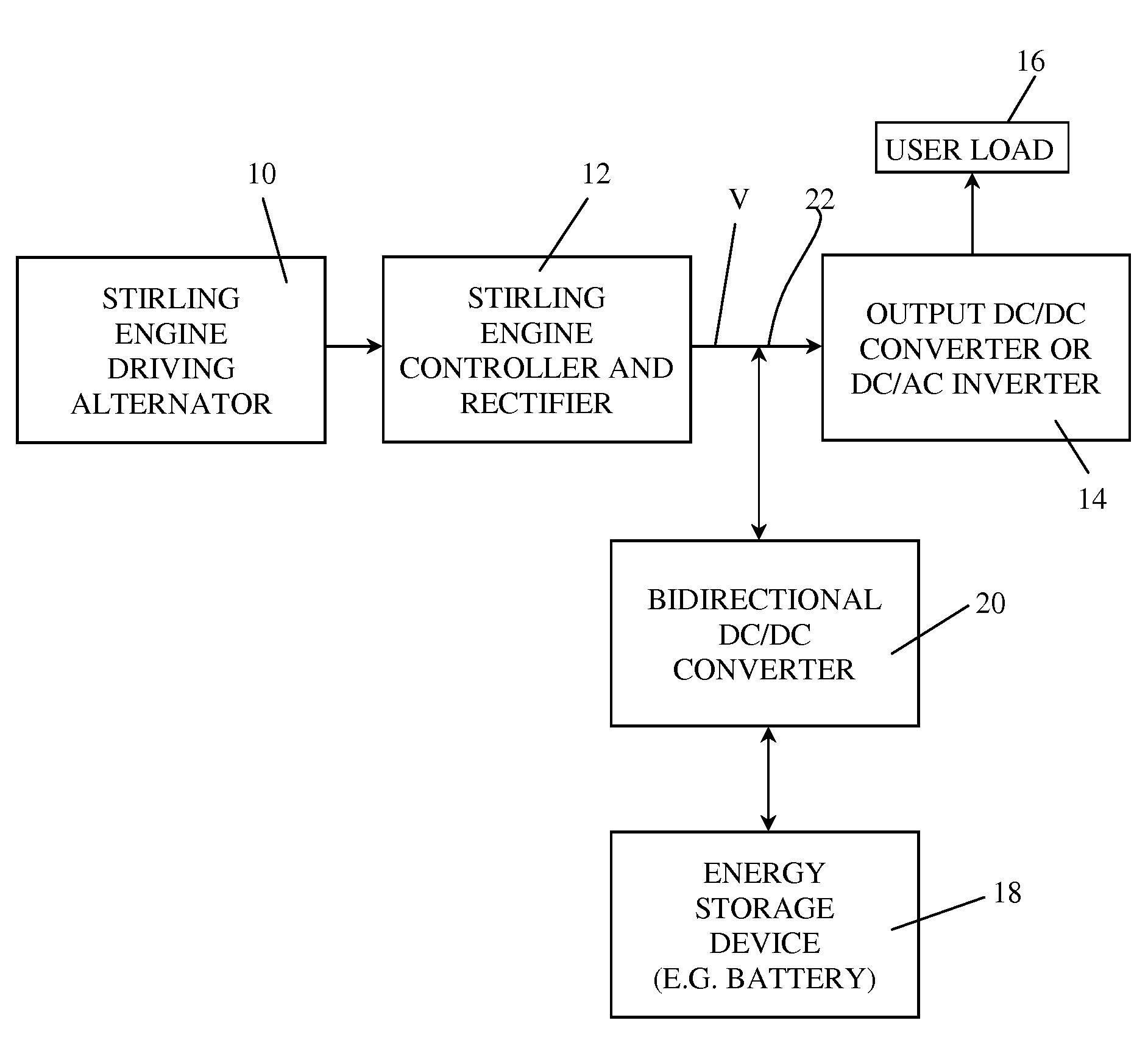
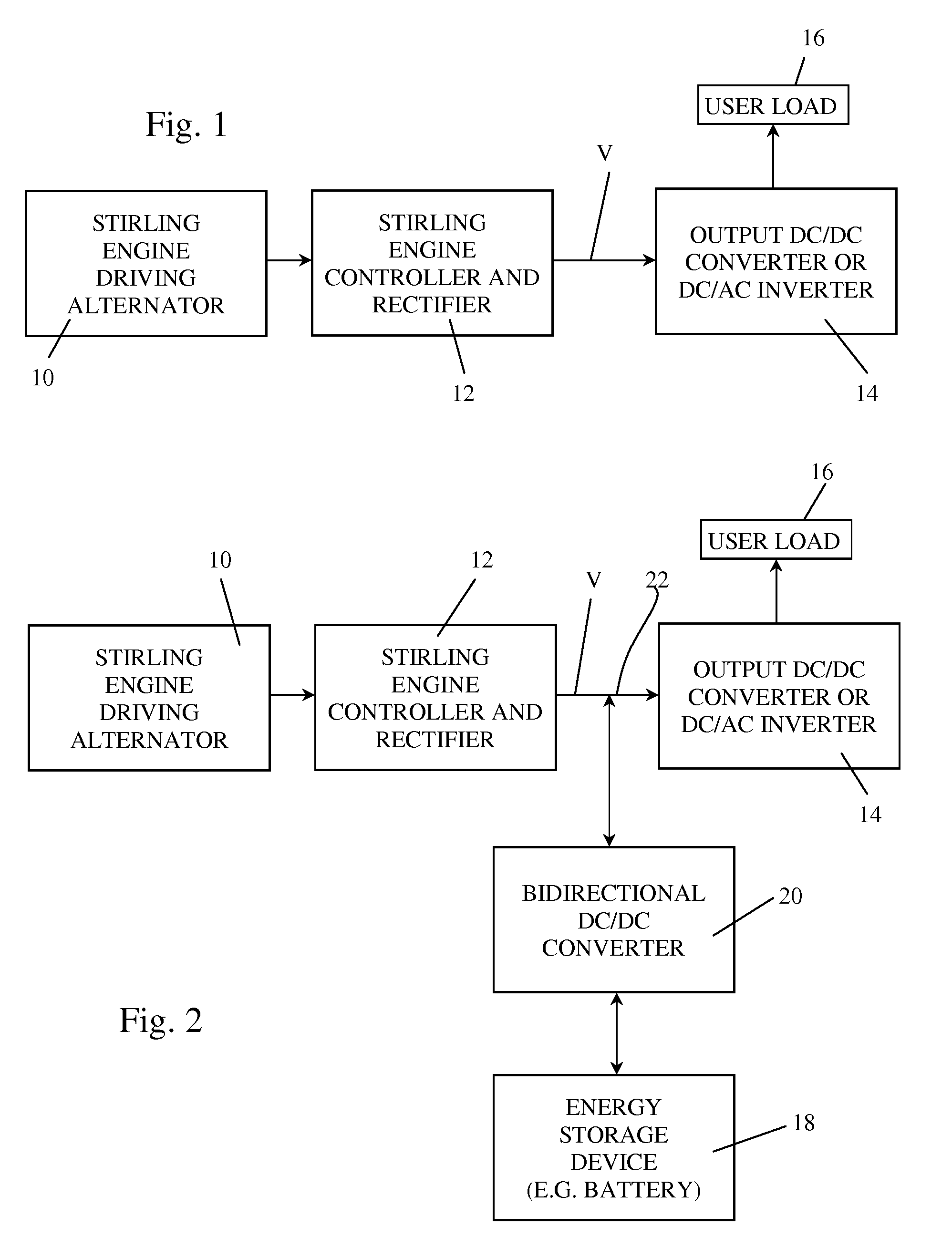
[0030]FIG. 1 illustrates an electrical power generating system that includes a free-piston Stirling engine driven alternator 10 and is known in the prior art. The free-piston Stirling engine is the subject of many patents and other public disclosures and includes a piston and displacer that are driven in periodic reciprocation by the application of heat to the heat accepting portion of the engine and removal of heat from the heat rejecting portion of the engine. The Stirling engine and the alternator that it drives are advantageously integrated in the same frame or case. A combination Stirling engine driving an alternator and its controller and rectifier that is suitable for use in embodiments of the present invention is illustrated and described in U.S. Pat. No. 7,453,241 which is herein incorporated by reference. An alternative combination Stirling engine driving an alternator and its controller and rectifier that is suitable for use in embodiments of the present invention is illu...


PUM


Abstract

An electrical power source including a free-piston Stirling engine driving an alternator to supply power through a bus to a user load and controlled by an engine/alternator controller. A bidirectional DC/DC converter is connected between a battery and the bus. The stroke of the engine piston is modulated between a maximum and a minimum stroke to maintain the bus voltage at a design nominal bus voltage (V1), and charge the battery if it is not charged, when and so long as the bus voltage does not fall below a design nominal bus voltage (V1). The Stirling engine is operated at its maximum piston stroke, and the battery is charged if it is not charged, when the bus voltage is in the range between the design nominal bus voltage (V1) and a design minimum battery charging bus voltage (V2). The Stirling engine is operated at its maximum piston stroke and the battery is disconnected from the bus so it can not charge when the bus voltage is in the range between the design minimum battery charging bus voltage (V2) and a design minimum bus voltage (V3). The Stirling engine is operated at its maximum piston stroke and power is applied from the battery to the bus for maintaining the bus voltage at the design minimum bus voltage (V3) when the power supplied from the alternator operating at its maximum stroke is less than the power demand of the load.

Description

CROSS-REFERENCES TO RELATED APPLICATIONS[0001]This application claims the benefit of U.S. Provisional Application No. 60 / 992,487 filed Dec. 5, 2007.STATEMENT REGARDING FEDERALLY-SPONSORED RESEARCH AND DEVELOPMENT[0002]This invention was made with Government support pursuant to a subcontract under contract RTI 05-1-11-15-050 awarded by US Army CECOM RDEC. The Government has certain rights in the invention.REFERENCE TO AN APPENDIX[0003](Not Applicable)BACKGROUND OF THE INVENTION[0004]1. Field of the Invention[0005]This invention relates generally to portable or transportable electrical power supply systems such as fuel driven generators and batteries and more particularly relates to a hybrid combination of a power generating system having an alternator driven by a Stirling engine and a storage battery or other device for storing electrical energy.[0006]2. Description of the Related Art[0007]An extensive variety of electrical power supply systems have been known in the prior art for we...

Claims


Application Information

Patent Timeline
Patent Type & Authority Applications(United States)
IPC IPC(8): H02J7/34H02J7/00H02P9/04
CPCF02G1/0435H02P9/04F02G2280/10F02G1/045
Inventor HOLLIDAY, EZEKIEL S.
Owner SUNPOWER
Why Eureka
Try Eureka