Mechanical/Thermo-Voltaic Solar Power System

Inactive Publication Date: 2008-04-03
JOHNSON D ALAN E
View PDF4 Cites 28 Cited by
  • Summary
  • Abstract
  • Description
  • Claims
  • Application Information

AI Technical Summary

Benefits of technology

[0026] It is another object of the present invention to provide a new and improved mechanical/thermo-voltaic solar power system that may be easily and efficiently manufactured and marketed.
[0027] An even further object of the present invention is to provide a new and improved mechanical/thermo-voltaic or thermopile solar power system that has a low cost of manufacture with regard to both mat

Problems solved by technology

Additionally, this patent does not disclose any use of alternative sources of heating and cooling.

Method used


Image

  • Mechanical/Thermo-Voltaic Solar Power System
  • Mechanical/Thermo-Voltaic Solar Power System
  • Mechanical/Thermo-Voltaic Solar Power System

Examples


Embodiment Construction

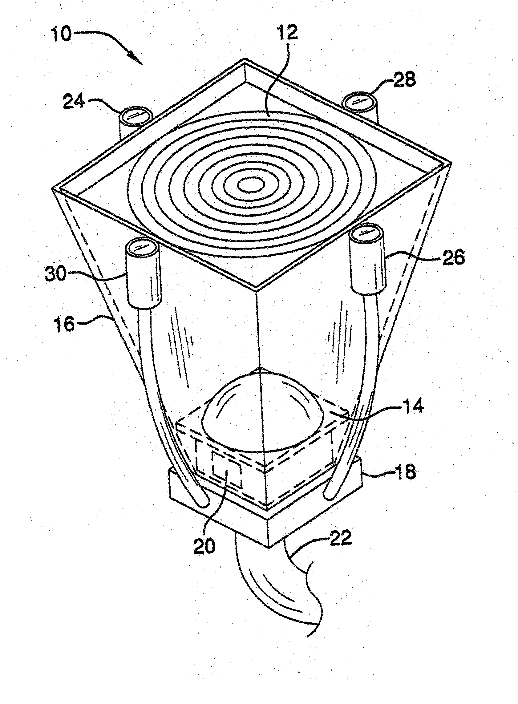
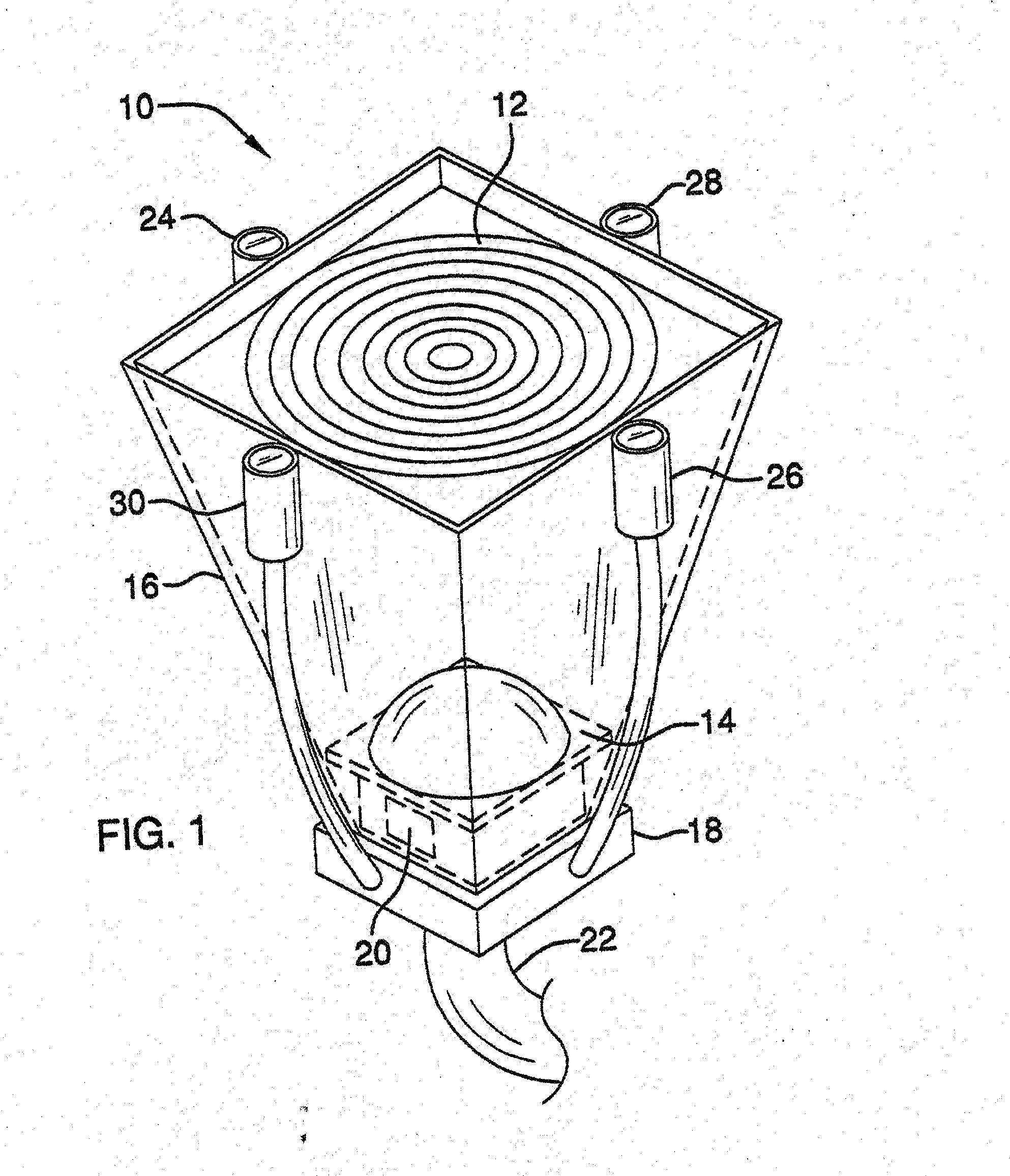
[0039] Referring now to the drawings, and particularly to FIGS. 1-7, a preferred embodiment of the mechanical / thermo-voltaic solar power system of the present invention is shown and generally designated by the reference numeral 10.

[0040]FIG. 1 is a perspective drawing of the light collection element 10 used in the preferred embodiment of the mechanical / thermo-voltaic solar power system constructed in accordance with the principles of the present invention. The system is essentially comprised of three major subsystems: (1) the solar collector array, (2) a mechanical / thermo-voltaic generator, and (3) a storage and retrieval system, with the solar collector array along with the combination of these three subsystems being central to the invention. More particularly, the solar collector array is comprised of an area array of light collector elements 10, which can be mounted in an area that receives good daylight, such as an open field or a roof. Each collector element 10 is comprised of...


PUM


Abstract

A mechanical/thermo-voltaic solar power system (MeTSoPoS) that uses a thermopile generator, instead of the photovoltaic panel commonly in use today, is disclosed. The system is comprised of three major subsystems: (1) a light collector array, (2) a thermopile thermo-voltaic generator, and (3) a storage and retrieval system. At the center of the system is the light collection array comprised of solar collector elements. These collector elements are connected to optical conduits (fiber optic cables) that carry the light energy to a thermo-electrical generator, such as a thermopile or a thermo-mechanical engine couple with an electrical generator. An automatic aiming system is used to align the collector elements directly at a light source for maximum light output. Each light collector element is comprised of a set of lenses that focus a larger area of light down to a point small enough to inject into an optical conduit. The optical conduit is then used to carry the light from each collector element to the generator. The heating chamber involves an outer shell where the optical conduits attach and allows the light to shine through to the heating area of either the boiler of a steam turbine, the hot node of a Stirling engine or thermopile. Additionally, a small hole is provided in the bottom of the heating chamber where a gas burner is mounted to provide an auxiliary means of providing heat to the system. The burner can be fueled by natural gas or from stored hydrogen from the system. Electricity from the system that is not used immediately is redirected to a storage unit, such as a bank of batteries. In the system, electricity can be taken directly form the generator or can be used to charge the batteries and taken from them when needed. The overall system has a means of monitoring the amount of energy being generated and if that is less than is being used for auto aiming and other nonessential functions, it will shut down those functions and switch into energy retrieval mode. A flow controller can be used to improve performance and runtime of the system by managing the flow of a thermally conductive fluid through various thermal exchange loops and then through the hot and/or cold nodes of the system.

Description

PRIORITY [0001] The present invention is a continuation in part of U.S. patent application Ser. No. 10 / 646,056 which was filed on Aug. 22, 2003.BACKGROUND OF THE INVENTION [0002] 1. Field of the Invention [0003] The present invention relates to a mechanical / thermo-voltaic solar power system for use in connection with home, business, industrial power generation or for portable and mobile applications. The mechanical and thermopile thermo-voltaic solar power system has particular utility in connection with generating power in a cleaner, safer, and more efficient way. [0004] 2. Description of the Prior Art [0005] Clean and efficient power generation is a growing concern in today's world. As the demand for more electricity to supply homes, businesses, and industry there is a continuing effort to also protect the environment. Although photovoltaic solar power generation is making strides towards providing cleaner power, there is the need towards improving the efficiency of such power gen...

Claims


Application Information

Patent Timeline
IPC IPC(8): H01L35/00F03G6/06H01L35/30
CPCF03G6/065Y02E10/46F03G6/068F03G6/06F03G6/003F03G6/04H10N10/00H10N10/13
Inventor JOHNSON, D. ALAN E.
Owner JOHNSON D ALAN E
Why Eureka
Try Eureka