Gas distribution piston type Stirling engine
A Stirling engine and gas distribution piston technology, which is applied to hot gas variable displacement engine devices, machines/engines, mechanical equipment, etc., to achieve the effects of reducing heat loss, increasing life, and reducing useless volume
- Summary
- Abstract
- Description
- Claims
- Application Information
AI Technical Summary
Problems solved by technology
Method used
Image
Examples
specific Embodiment approach 1
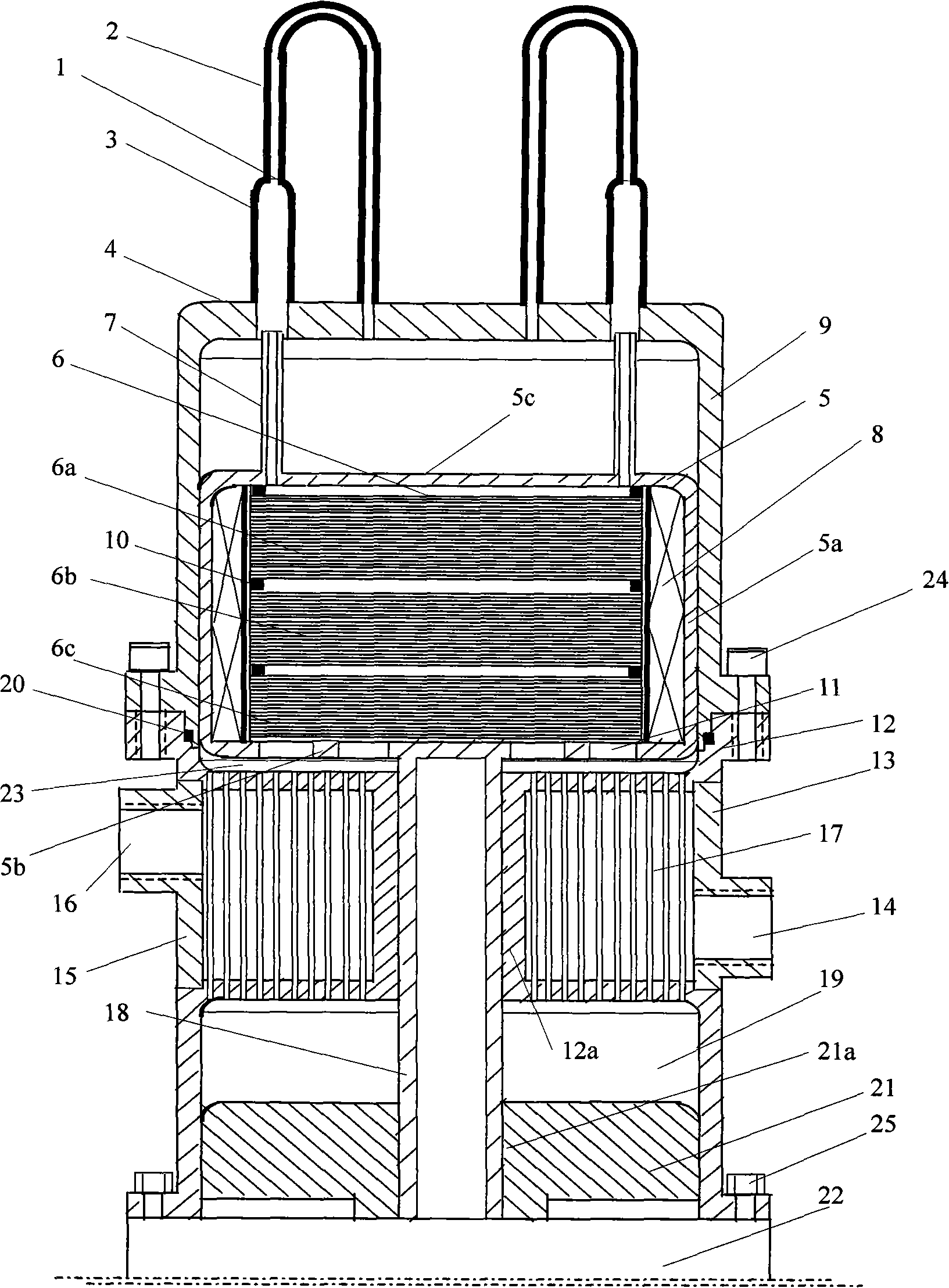
[0043] exist figure 1 In the illustrated embodiment:
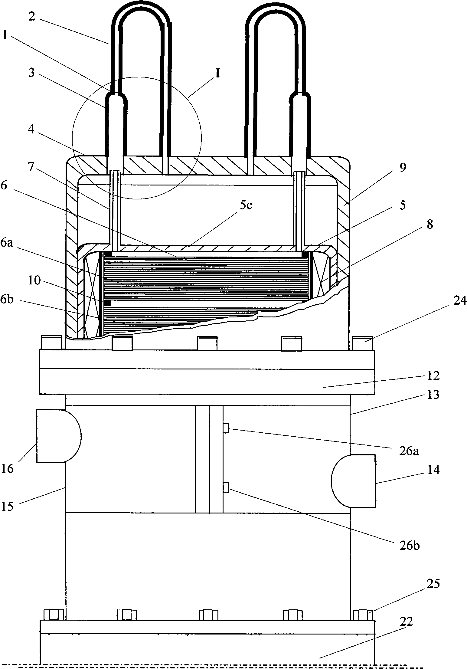
[0044] Gas distribution piston Stirling engine, which includes a heating tube 1, a hot chamber cylinder 9, a gas distribution piston 5, a regenerator 6, a cold chamber cylinder 23 and 19, and a cooler 12, wherein:
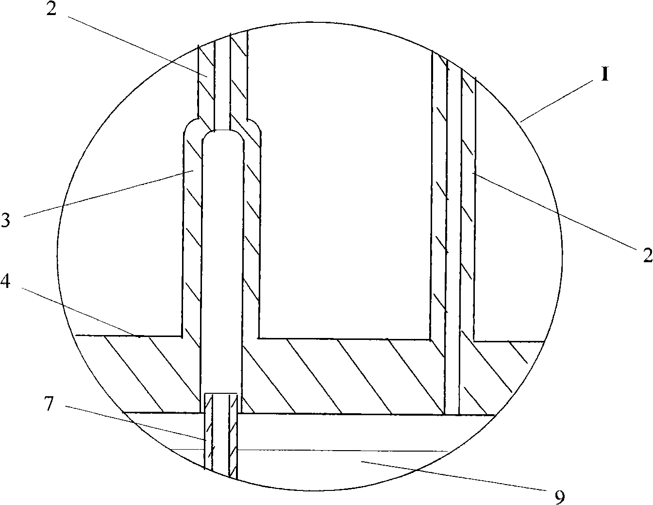
[0045] The heating tube 1 is composed of a tube 2 and a sleeve 3, and a plurality of identical heating tubes 1 form a heater tube group; one end of the tube 2 and the sleeve 3 is airtightly connected, and the other end of the sleeve 3 is vertically airtightly connected at a temperature smaller than the heat On the top 4 outside the hot chamber cylinder 9 corresponding to the cylinder bore section of the chamber cylinder 9 and communicated with the inside of the cylinder bore 9, the other end of the pipe 2 is vertically airtightly connected to the area corresponding to the cylinder bore section of the hot chamber cylinder 9. On the top 4 outside the hot chamber cylinder 9, and communicate with the inside of the...
specific Embodiment approach 2
[0052] exist Figure 9 In the illustrated embodiment:
[0053] An inner tube 27 concentric with the sleeve 3 is arranged in the sleeve 3, and one end of the inner tube 27 is airtightly connected to the inner joint surface of the sleeve 3 and the tube 2, and the other end of the inner tube 27 is connected to the top of the hot chamber cylinder 9 4 flush with the bottom surface. The wall thickness of the inner tube 27 is 0.2-1 mm, the inner diameter is approximately equal to the inner diameter of the tube 2, and the outer diameter is about 0.2 mm smaller than the inner diameter of the draft tube 7. The guide tube 7 is inserted in the tubular space 30 between the casing 3 and the inner tube 27, and the depth of the tubular space 30 is 1 to 2 mm greater than the stroke of the gas distribution piston 5; when the guide tube 7 reciprocates in the tubular space 30, The air pressure difference between the inner wall 29 and the outer wall 28 of the draft tube 7 is small at the same po...
specific Embodiment approach 3
[0055] exist figure 1 In the illustrated embodiment:
[0056] The regenerator 6 is divided into two or more sub-regenerators 6a, 6b, 6c in the axial direction, and the heat-insulating ring gasket 10 is arranged between the sub-regenerators 6a, 6b, 6c to form a multi-stage series connection regenerator. The multi-stage series regenerator reduces the heat loss of the regenerator 6 in the axial direction, increases the temperature gradient of the regenerator 6 in the axial direction, and thus increases the efficiency of the regenerator 6 . The heat insulating ring pad 10 can also be a sheet-like mesh structure, which can be made of materials with low thermal conductivity, such as ceramics.
PUM
 Abstract
Description
Claims
Application Information
 - R&D
- Intellectual Property
- Life Sciences
- Materials
- Tech Scout
- Unparalleled Data Quality
- Higher Quality Content
- 60% Fewer Hallucinations
Browse by: Latest US Patents, China's latest patents, Technical Efficacy Thesaurus, Application Domain, Technology Topic, Popular Technical Reports.
© 2025 PatSnap. All rights reserved.Legal|Privacy policy|Modern Slavery Act Transparency Statement|Sitemap|About US| Contact US: help@patsnap.com


