Stirling engine burner

a technology of engine burner and burner body, which is applied in the direction of hot gas positive displacement engine plants, fuel injection apparatuses, charge feed systems, etc., can solve the problems of reducing the efficiency of heat exchange aspects of burners and the complexity of manufacture or construction of burners

Inactive Publication Date: 2001-04-24
WHISPER TECH LTD
View PDF5 Cites 24 Cited by
  • Summary
  • Abstract
  • Description
  • Claims
  • Application Information

AI Technical Summary

Benefits of technology

In the preferred form of the invention there is provided heat exchange means whereby inlet air, after having applied a cooling effect to the housing, is heated before being directed to the shroud. Preferably, the heat exchange means has inlet means for receiving exhaust gases from the combustion chamber, and outlet means connected to the gas exhaust means.

Problems solved by technology

However these three burners have a limited amount of thermal connection between the inlet air and exhaust gases, reducing the efficiency of the heat exchange aspects of the burner.
A further difficulty of the disclosed burners is the complexity of manufacture or construction of the burner disclosed.

Method used


Image

  • Stirling engine burner
  • Stirling engine burner
  • Stirling engine burner

Examples


Embodiment Construction

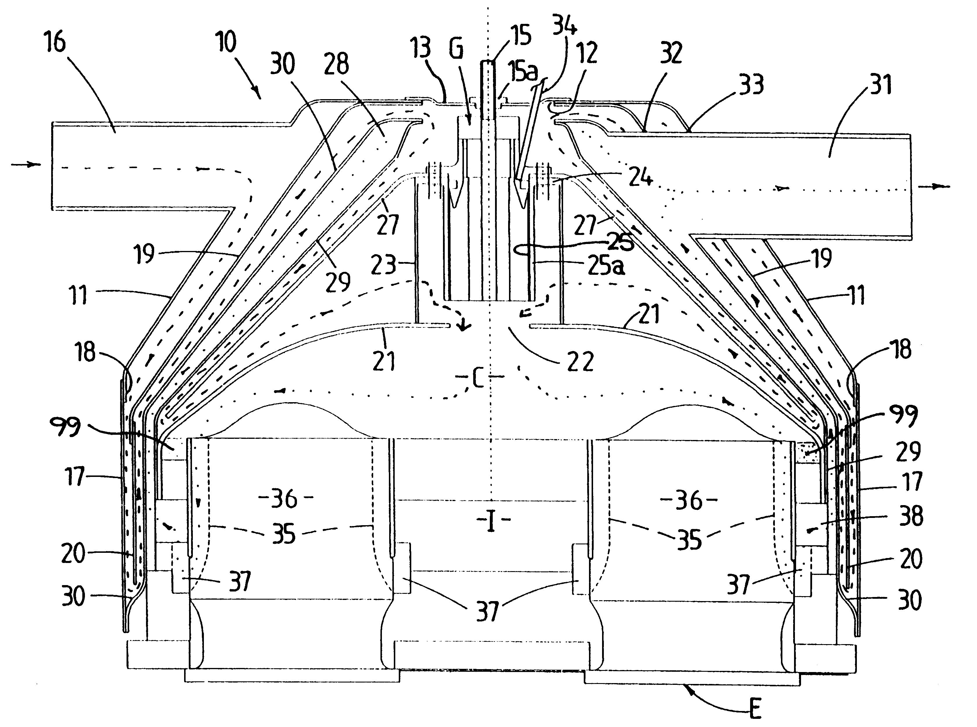
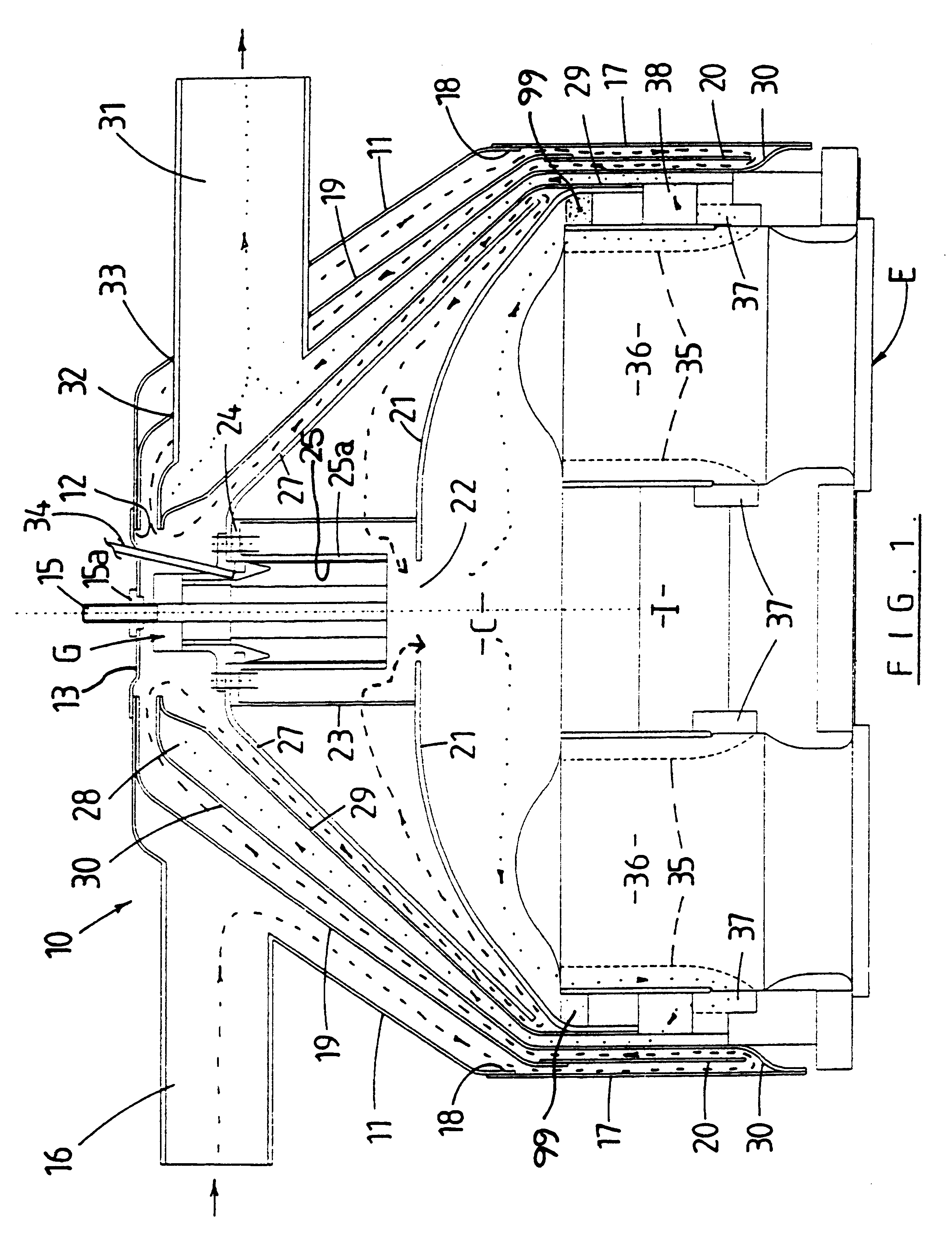
Referring to FIG. 1, a burner 10 for a Stirling cycle engine E is there shown. The burner 10 is primarily formed from sheet steel. As will become apparent from the following description, many of the components can be fabricated by the known technique of metal spinning.

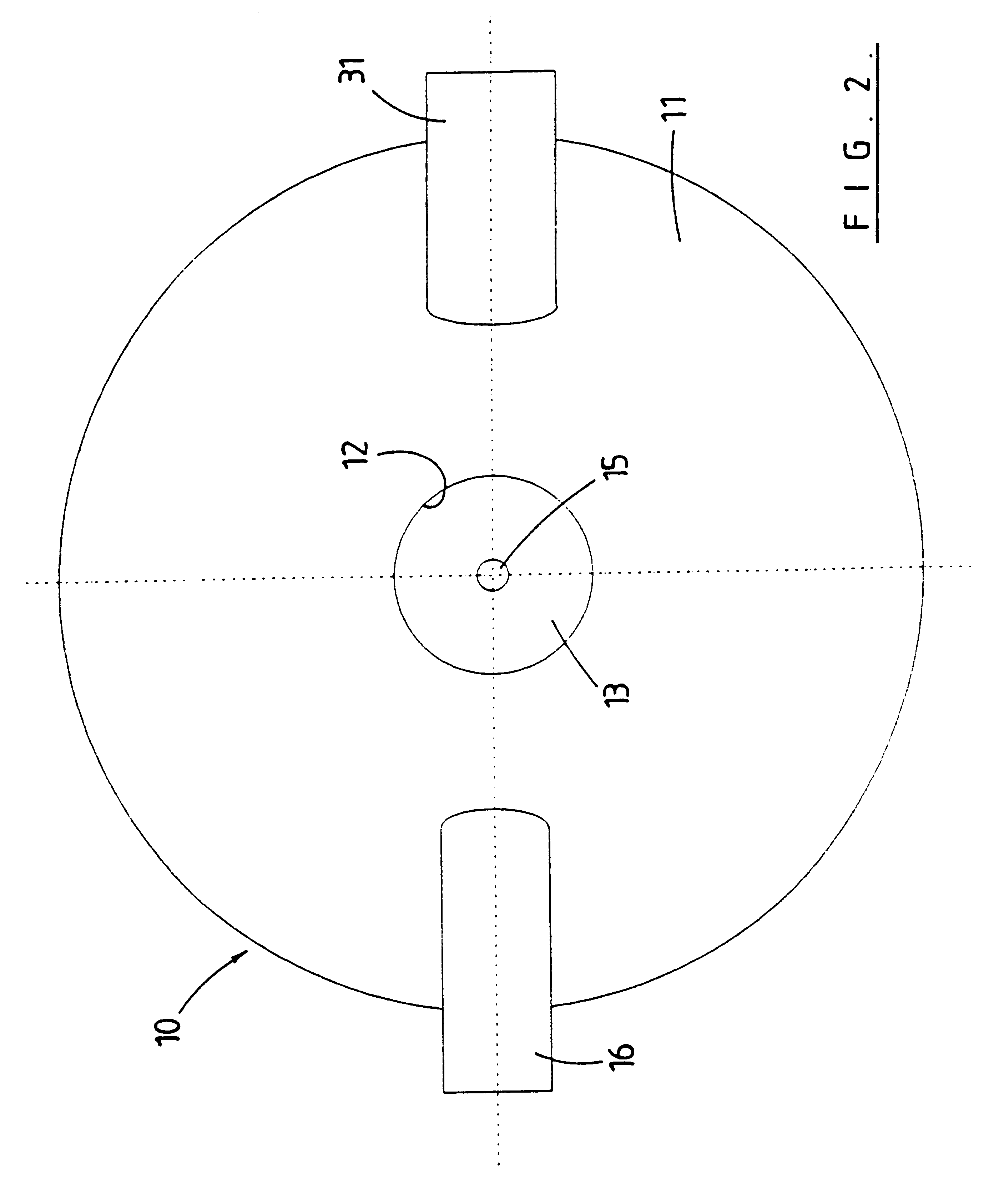
Referring to both the FIGS. 1 and 2, the burner 10 includes an outermost or external housing 11. The external housing 11 can be generally described as being a shell which is substantially of an inverted dish shape. In the drawings and in the description following, the `base` of the inverted dish is uppermost, so that the sides of the external housing 11 slope upwardly and inwardly.

However, it will be appreciated by those skilled in the art that the burner 10 can be at any orientation; the description of the `base` of the shell of the housing 11 as being uppermost being used here only as an example and for ease of description of the elements of the burner 10.

A central opening 12 is formed in the external housing 11 whic...


PUM


Abstract

A burner for an external combustion engine using liquid or gaseous fuel, the burner being arranged for heat exchange between the inlet air to the burner and the exhaust air from the burner. The burner includes an external housing, a shroud within this housing, which shroud forms part of the centrally positioned combustion chamber. The burner includes air inlet apparatus and guide apparatus for guiding the inlet air to the combustion chamber, an igniter and fuel inlet apparatus and gas exhaust apparatus. The external housing, an element of the inlet apparatus, the guide apparatus, and heat exchange elements are formed as inverted shaped dishes or shells about the combustion chamber.

Description

This invention relates to a burner. The present invention is more particularly concerned with a burner for use in a heat exchange arrangement. It is particularly suitable for use with an external combustion engine where the engine is powered by a heat source and is not fuel dependent.With an external combustion engine the heat developed from combustion of fuel in the burner is transferred through a heat exchanger to the working fluid of the engine. Such an external combustion engine can, for example, be one which operates on a Stirling Cycle.A Stirling Cycle engine operates on a closed thermodynamic cycle in which one mass of gas is repeatedly expanded and compressed. Unlike an internal combustion engine, there are no valves, intake or exhaust ports, and no combustion in the cylinders. The engine therefore has very low noise output and can be dynamically balanced, thereby resulting in virtually no engine vibration. Little maintenance is required because the combustion products are k...

Claims


Application Information

Patent Timeline
Patent Type & Authority Patents(United States)
IPC IPC(8): F02G1/055F02G1/00F02M61/02
CPCF02G1/055F02G2255/20
Inventor CLUCAS, DONALD MURRAYMENTINK, GEOFFREY JAMES
Owner WHISPER TECH LTD
Why Eureka
Try Eureka