Fluid injection device and medical instrument including fluid injection device

a technology of fluid injection device and fluid injection chamber, which is applied in the direction of positive displacement liquid engine, process and machine control, instruments, etc., can solve the problems of easy deterioration or decrease of inability to achieve appropriate fluid injection through pressurization of the fluid within the fluid chamber, etc., to achieve secure high-level safety, maintain maneuverability of the fluid injection device, and not deteriorate

a technology of fluid injection device and fluid injection chamber, which is applied in the direction of positive displacement liquid engine, process and machine control, instruments, etc., can solve the problems of easy deterioration or decrease of inability to achieve appropriate fluid injection through pressurization of the fluid within the fluid chamber, etc., to achieve secure high-level safety, maintain maneuverability of the fluid injection device, and not deteriorate

US20120046605A1Active Publication Date: 2012-02-23COLUMBIA PEAK VENTURES LLC

Image

  • Fluid injection device and medical instrument including fluid injection device
  • Fluid injection device and medical instrument including fluid injection device
  • Fluid injection device and medical instrument including fluid injection device

Examples


Embodiment Construction

[0038]Embodiments of the invention are hereinafter described in the following order for clarifying the details of embodiments the invention.

[0039]1. Device Structure

[0040]2. Fluid Injection Operation

[0041]3. Actuator Driving Method

[0042]4. Modification of Embodiment

1. Device Structure

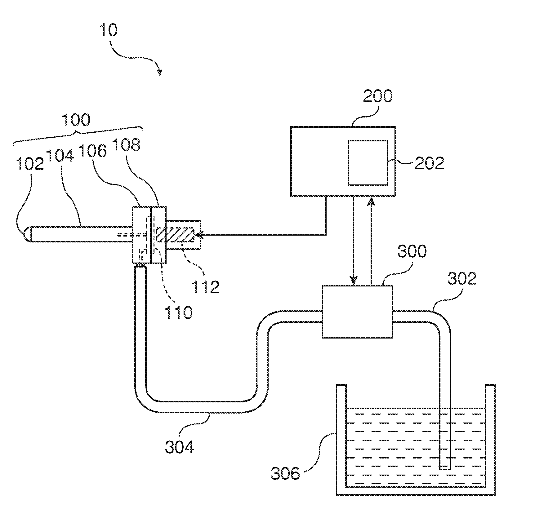
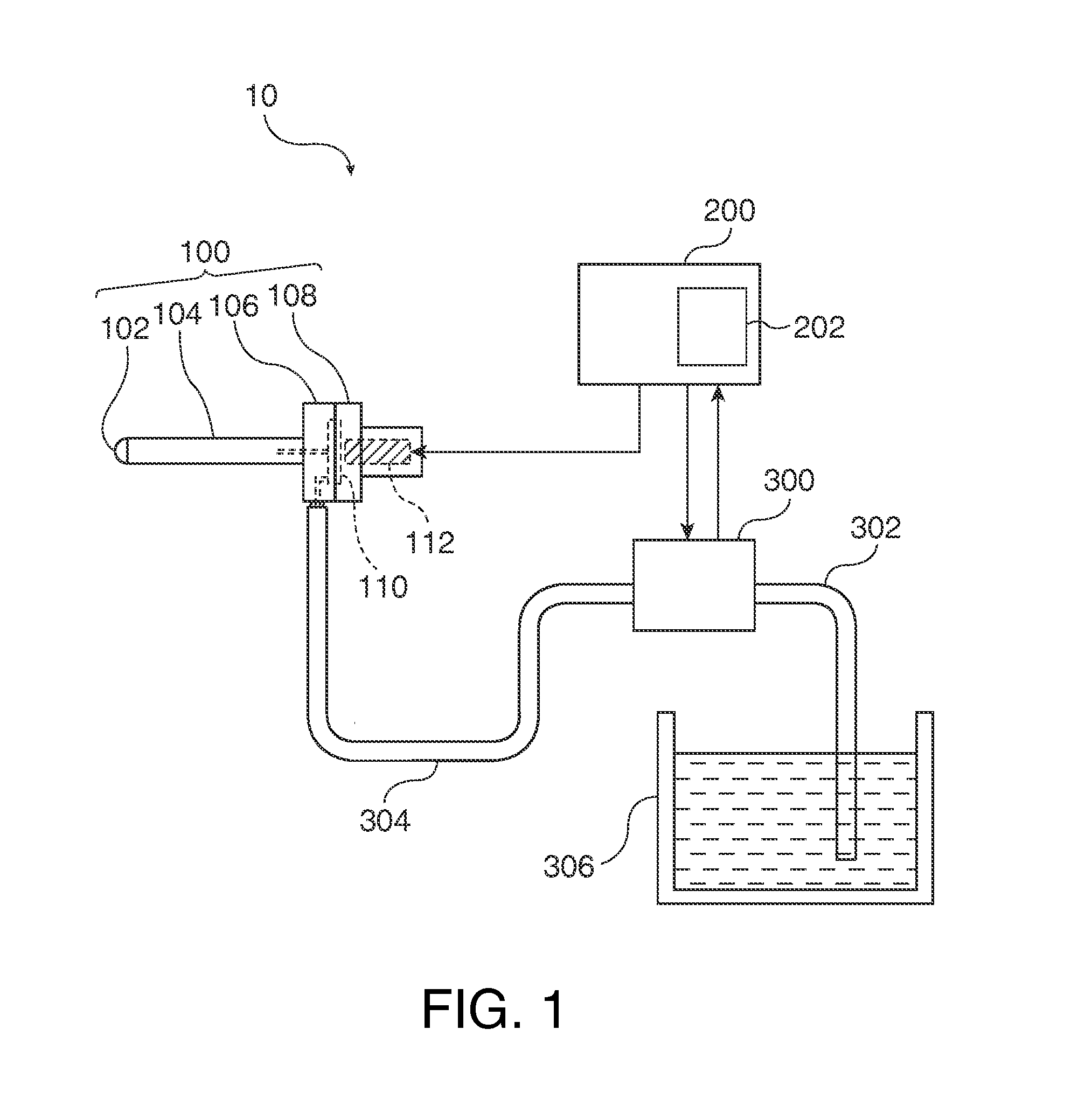
[0043]FIG. 1 schematically illustrates a general structure of a fluid injection device 10 according to this embodiment. As illustrated in FIG. 1, the fluid injection device 10 includes an injection unit 100 which ejects fluid in pulses, a supply pump 300 as a fluid pressurizing and supplying unit which pressurizes fluid and supplies the fluid to the injection unit 100 as fluid to be ejected from the injection unit 100, a control unit 200 which controls the operations of the injection unit 100 and the supply pump 300, and a memory section 202 as a memory unit which stores the pressure fluctuations of the supply from the supply pump 300 in advance. The memory section 202 may be contained in the control un...


PUM


Abstract

Fluid is pressurized and supplied to a fluid chamber with a fluid pressurizing and supplying unit. The pressurized fluid within the fluid chamber is ejected through an injection nozzle by reduction of the volume of the fluid chamber caused by applying a driving voltage to a volume varying unit. In applying the driving voltage to the volume varying unit, the effect imposed on fluid injection by pressure fluctuations of the fluid pressurized and supplied to the fluid chamber is compensated by changing the voltage waveform of the driving voltage. When the pressure of the supply flow amount is decreased to a pressure lower than a predetermined pressure, the time intervals of the driving waveform are corrected. The maneuverability of a fluid injection device does not deteriorate even when the pressure of the fluid pressurized and supplied to the fluid chamber fluctuates.

Description

[0001]This application claims the benefit of priority to Japanese Application No. 2010-184761 filed Aug. 20, 2010, which application is incorporated by reference in its entirety.BACKGROUND[0002]1. Technical Field[0003]Embodiments of the present invention relate to a fluid injection device which ejects pressurized fluid, and to a medical instrument including the fluid injection device.[0004]2. Related Art[0005]Technology has been developed that pressurizes fluid such as water and physiological saltwater and ejects the fluid toward living tissues or the like through an injection nozzle for incision or excision of the living tissues or for other purpose (JP-A-2005-152127). This technology can incise the target tissues, such as internal organs, without damaging vascular structures such as blood vessels, and can thus reduce injuries to the surrounding tissues. Accordingly, this technology is expected to decrease the burden of surgery performed on a patient.[0006]In addition, a technology...

Claims


Application Information

Patent Timeline
23 Feb 2012
Publication
US20120046605A1
IPC
A61M5/168
CPC
A61B17/3203; F04B43/04; A61M5/30; A61M5/168; A61B2017/00185; A61B2017/0019
Inventors
UCHIDA, KAZUAKI; KOJIMA, HIDEKI