Supercharge Your Innovation With Domain-Expert AI Agents!

Interspinous spacer and facet joint fixation device

a technology of interspinous spacer and facet joint, which is applied in the field of spinal surgery, can solve the problems of spinal nerve root pressure, intervertebral discs and other parts of the spinal column deteriorating, severe and even debilitating pain,

Active Publication Date: 2012-02-23
WARSAW ORTHOPEDIC INC
View PDF5 Cites 55 Cited by
  • Summary
  • Abstract
  • Description
  • Claims
  • Application Information

AI Technical Summary

Benefits of technology

[0009]According to a principal aspect of the present invention, an implantable device includes a spacer body that can be implanted between the spinous processes and between the articulating processes of a pair of adjacent vertebrae that are to be fused together. The spacer body supports the vertebrae in a desired relationship. A pair of fasteners such as screws extend through the spacer body, with each screw extending also through the facet joint on a respective lateral side of the spine so as to immobilize the facet joint and promote fusion between the cephalad / caudad lamina, spinous process, and facet joints.

Problems solved by technology

Lower back pain is commonly caused by deterioration of intervertebral discs and facet joints, resulting in stenosis of intervertebral foramina and thus causing pressure on spinal nerve roots where they exit from the spinal nerve canal and extend laterally away from the spine through the intervertebral foramina.
As people age, intervertebral discs and other parts of the spinal column deteriorate.
Pressure on nerve roots due to facet arthrosis, ligamentum flavum infolding, and disc herniations often results and can cause severe and even debilitating pain.
Degeneration of discs may also allow a vertebra to become misaligned with respect to an adjacent vertebra, resulting in spondylolisthesis.
Compared with facet fixation, pedicle screws and rod insertions requires a longer operative time, and results in increased blood loss, and increased paraspinal muscle trauma.
Such clamps can be attached so as to distract the vertebrae from each other, but because of the location of such a clamp, spaced apart dorsally from the deteriorated intervertebral discs, use of such a clamp may result in reduced lordosis, thereby resulting in additional strain experienced by joints between other vertebrae.
Such clamp devices, moreover, often cannot be used in an L5-S1 location, because of the lack of a large enough spinous process on the sacrum.
Additionally, the interconnected spinous processes may fail under the forces applied through such clamps.

Method used


Image

  • Interspinous spacer and facet joint fixation device
  • Interspinous spacer and facet joint fixation device
  • Interspinous spacer and facet joint fixation device

Examples


Embodiment Construction

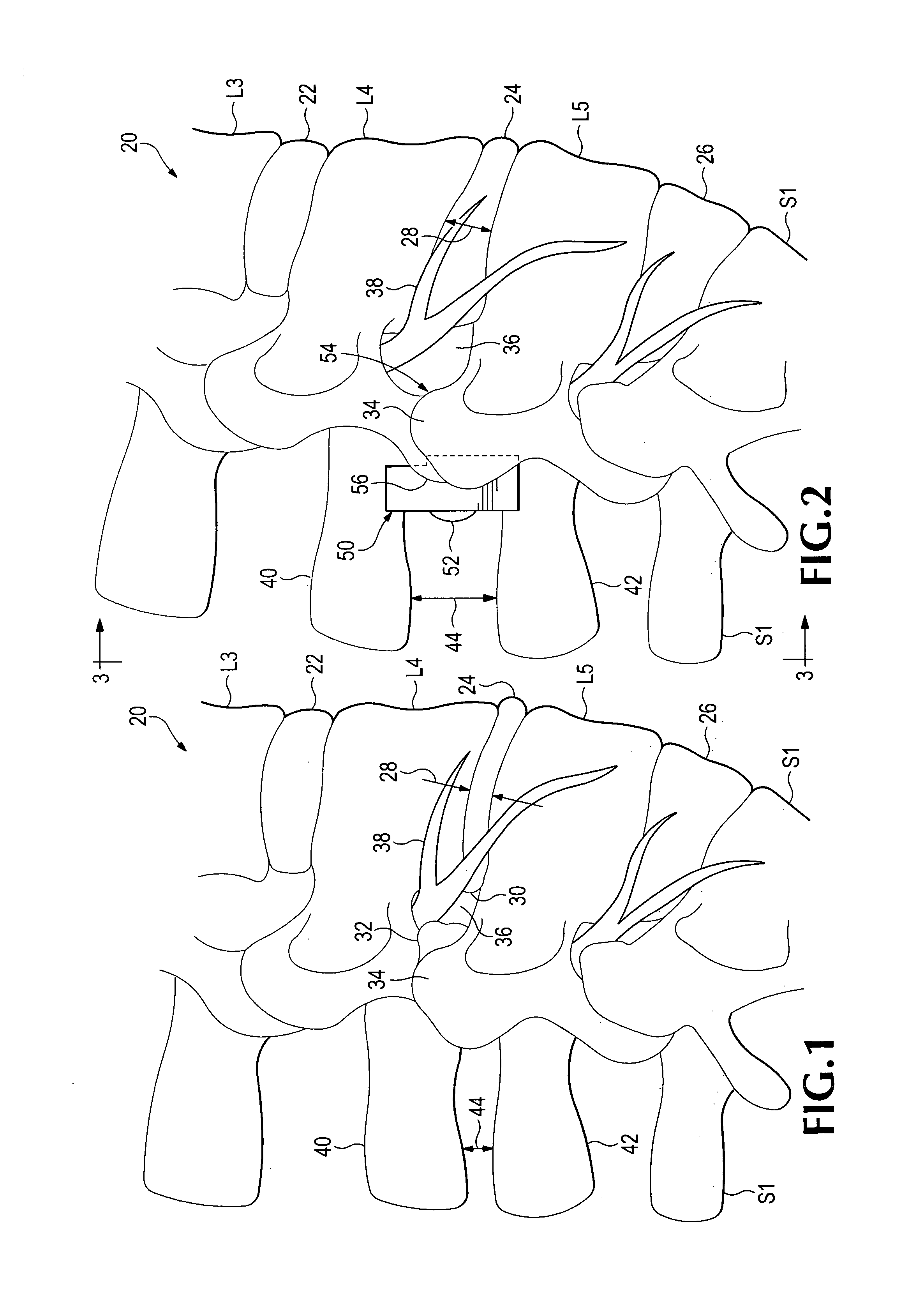
[0029]Referring now to the drawings which form a part of the disclosure herein, in FIG. 1 a part of a spinal column 20 is seen in profile from the right lateral side. The illustrated part of the spinal column includes a sacrum S1 and lumbar vertebrae L5, L4, and L3. Intervertebral discs 22, 24, and 26 separate the vertebrae from one another and, in a healthy individual, maintain sufficient spacing between adjacent vertebrae.

[0030]In the spinal column 20 as shown in FIG. 1, however, the disc 24 between the L4 and L5 vertebrae has deteriorated and has allowed the spacing 28 between the L4 and L5 vertebrae to decrease markedly from normal spacing. The L4 vertebra has also been able to move ventrally with respect to the L5 vertebra, and the disc 24 is herniated and has bulged in a dorsal direction, as shown at 30. The superior articulating process 34 of the L5 vertebra has become hypertrophied, and an osteophyte, or bone spur 32 protrudes from it toward the nerve root 38.

[0031]The combi...


PUM


Abstract

A biologically implantable device including a spacer body and fasteners for fixing the spacer body in place between vertebrae, and a method for use of the device to improve intervertebral spacing and correct foraminal stenosis, and to immobilize facet joints and promote fusion of adjacent vertebrae to each other. A drill guide may be used in providing bores in the facet joints to receive the fasteners.

Description

TECHNICAL FIELD[0001]The present invention relates to spinal surgery, and in particular relates to an implantable device and a procedure for use of such a device in fusing vertebrae together.BACKGROUND ART[0002]Lower back pain is commonly caused by deterioration of intervertebral discs and facet joints, resulting in stenosis of intervertebral foramina and thus causing pressure on spinal nerve roots where they exit from the spinal nerve canal and extend laterally away from the spine through the intervertebral foramina. As people age, intervertebral discs and other parts of the spinal column deteriorate. Discs may shrink, allowing vertebrae to approach one another more closely, and facet joints may develop bone spurs, protruding into the foramina and reducing the available space through which nerve roots must extend. Pressure on nerve roots due to facet arthrosis, ligamentum flavum infolding, and disc herniations often results and can cause severe and even debilitating pain. Degenerat...

Claims


Application Information

Patent Timeline
IPC IPC(8): A61F2/44
CPCA61B17/7064A61B17/7071A61B17/1757A61F2/442A61F2/4455
Inventor TATSUMI, ROBERT
Owner WARSAW ORTHOPEDIC INC
Features
  • R&D
  • Intellectual Property
  • Life Sciences
  • Materials
  • Tech Scout
  • Unparalleled Data Quality
  • Higher Quality Content
  • 60% Fewer Hallucinations
Learn More