Methods and apparatus for drying logs with microwaves using feedback and feed forward control
a technology of feedback control and log temperature, which is applied in the direction of ohmic-resistance heating, manufacturing tools, electric/magnetic/electromagnetic heating, etc., can solve the problems of short term variability and long term drift in the final log temperature, high energy consumption, and inconsistent product quality
- Summary
- Abstract
- Description
- Claims
- Application Information
AI Technical Summary
Benefits of technology
Problems solved by technology
Method used
Image
Examples
embodiment 1
Controller Embodiment 1
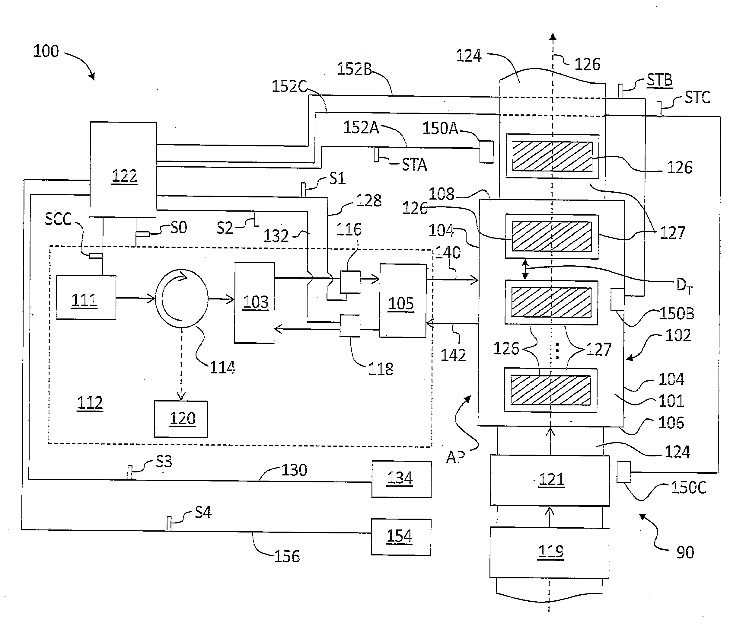
[0068]FIG. 6 is a schematic diagram of an example configuration for controller 122 shown in connection with some of the relevant components of microwave dryer system 100. Controller 122 includes a first controller unit 122-1 connected to temperature sensors 150A and is configured to determine (e.g., calculate) long-term shifts in the log temperature TL (e.g., the final log temperature TF) and to generate power adjustment information in the form of control signals SC1. First controller unit 122-1 is thus referred to as the “long term” or “LT” controller unit. LT controller unit 122-1 need only function relatively slowly because it executes the moving average calculation for the temperature variation at a relatively slow rate as the temperature measurements are made on the processed logs.
[0069]Controller 122 also includes a second controller unit 122-2 that determines the amount of dissipation power needed (i.e., the expected dissipated power) based on such fact...
embodiment 2
Controller Embodiment 2
[0078]A second example configuration for controller 122 has a single input and multiple outputs (SIMO), e.g., two outputs. FIG. 8 is a schematic diagram of the SIMO controller configuration formed using PI controller unit 122-4 and an additional controller unit 122-5 used to calculate the power ramp rate PRR using equation (11), below (controller 122-5 is thus referred to as the “PRR controller unit”). As with the first example controller configuration, the input to PI controller 122-4 is error signal Se representative of the error between the expected dissipated power and the measured dissipated power. The outputs are the change in the magnetron power ΔPmag as embodied in control signal SC4 and the power ramp rate PRR as provided by PRR controller unit 122-5 in the form of an electrical signal SPRR.
[0079]The change in the magnetron power ΔPmag is as described in either equation (10) above or equation (14) below, and the power ramp rate PRR is given as follows...
embodiment 3
Controller Embodiment 3
[0083]A third example configuration for controller 122 has two inputs and two outputs, i.e., is a multiple-input / multiple-output (MIMO) controller. The outputs are similar to the ones described in Controller Embodiment 2, namely, the combined control signal SCC and the power ramp rate PRR. However, the inputs to the controller are the error between the expected dissipated power and the measured dissipated power as represented by error signal Se, and the tray inch as embodied in an electrical signal S4, which provides an estimate of the load inside a particular applicator.
[0084]FIG. 10 is a schematic diagram of an example MIMO controller configuration similar to that of FIG. 8, except that PRR controller unit 122-5 receives tray inch signal S4 from the detector 154, for example (see FIG. 2). The change in the magnetron power ΔPmag is obtained as described in either equation (10) or equation (14) and the power ramp rate PRR is determined in PRR controller unit 1...
PUM
| Property | Measurement | Unit |
|---|---|---|
| Temperature | aaaaa | aaaaa |
| Power | aaaaa | aaaaa |
| Mass | aaaaa | aaaaa |
Abstract
Description
Claims
Application Information
 - R&D
- Intellectual Property
- Life Sciences
- Materials
- Tech Scout
- Unparalleled Data Quality
- Higher Quality Content
- 60% Fewer Hallucinations
Browse by: Latest US Patents, China's latest patents, Technical Efficacy Thesaurus, Application Domain, Technology Topic, Popular Technical Reports.
© 2025 PatSnap. All rights reserved.Legal|Privacy policy|Modern Slavery Act Transparency Statement|Sitemap|About US| Contact US: help@patsnap.com


