Handheld vision tester and calibration tehreof

a technology of vision testing and calibration tehreof, which is applied in the direction of diagnostic recording/measuring, instruments, applications, etc., can solve the problems of inability to detect the presence of vision test results, and inability to recover vision loss or even blindness,

Active Publication Date: 2012-03-01
GENENTECH INC
View PDF2 Cites 22 Cited by
  • Summary
  • Abstract
  • Description
  • Claims
  • Application Information

AI Technical Summary

Benefits of technology

[0005]To address the above-discussed deficiencies of the prior art, in one embodiment, there is provided a handheld vision tester. In this particular embodiment, the handheld vision tester comprises a display, cursor control, an interface port, and a camera. The display delivers visi

Problems solved by technology

Professional evaluation is effective in analyzing many vision disorders, but is expensive and may not be available in rural and remote areas.
Observation of vision testing charts is effective, but is bulky and cumbersome as the

Method used


Image

  • Handheld vision tester and calibration tehreof
  • Handheld vision tester and calibration tehreof
  • Handheld vision tester and calibration tehreof

Examples


Embodiment Construction

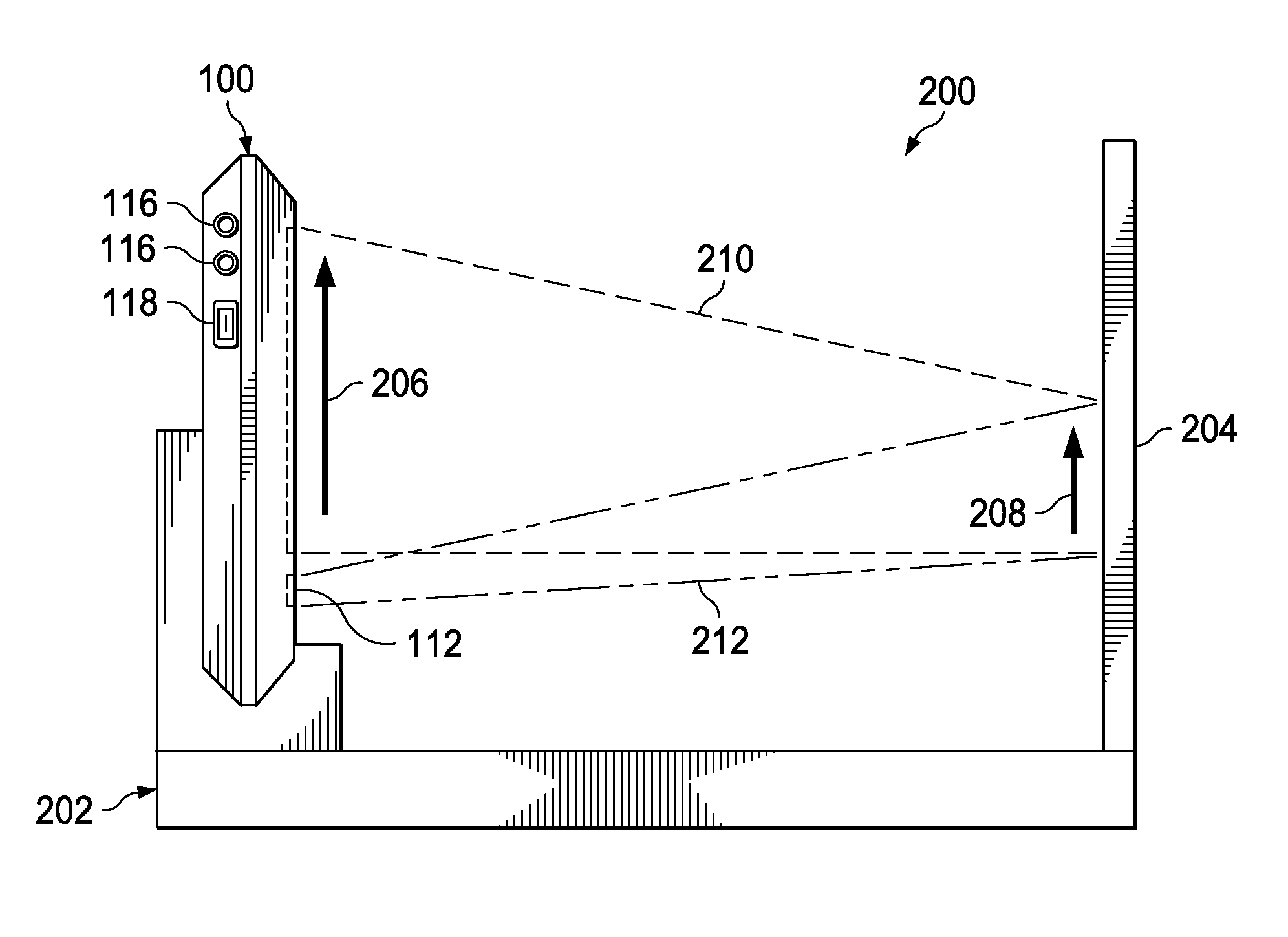
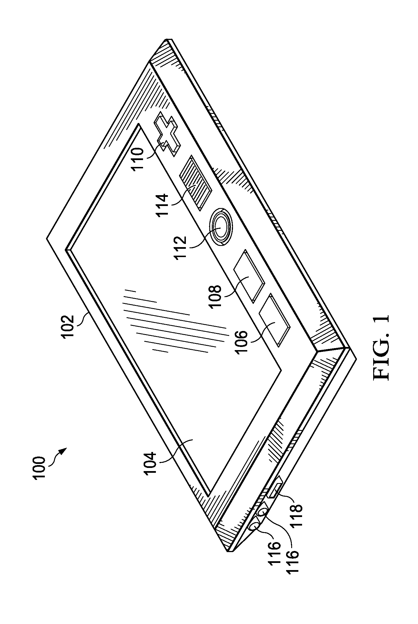
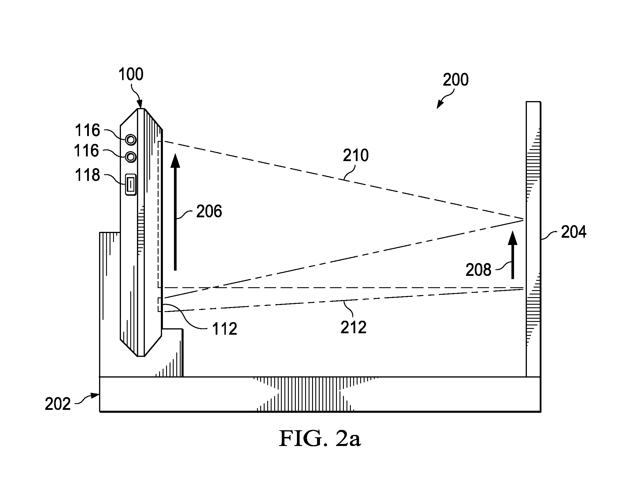
[0015]In FIG. 1, an electronic handheld device 100 is shown. The handheld device 100 may include a case 102, a display 104, a cursor control 110, a fingerprint sensor 114, a camera 112, a first button 106, a second button 108, a power connector 116, and an interface port 118. The display 104 may include touch-screen capability so that the handheld device 100 can be controlled by touching the display 104 in pre-specified locations or manners within certain timeframes. The fingerprint sensor 114 allows the handheld device 100 to identify the person using it. The cursor control 110 is a button that may be pressed to move a cursor across the display 104 and position it in a desired location. Pressing the cursor control 110 may also be used to trigger operations and to control the handheld device 100. Alternative implementations of cursor controls include track balls, joysticks, touch pads, and other approaches may also be used in place of the cursor control 110 as shown in FIG. 1. The f...


PUM


Abstract

In one aspect, there is provided a handheld vision tester comprising a display, cursor control, interface port, and camera. The display delivers a series of images making up vision tests to a user who interacts with the vision tests by using the display and cursor control of the handheld vision tester. The camera verifies the user is taking the vision tests. The results of the vision tests are stored in the handheld communication device. The interface port allows for communication of the stored results of the vision tests with external devices. In another aspect, there is provided a calibration system for the handheld vision tester. The calibration system includes a stand to hold the handheld vision tester and a reflective surface substantially parallel to a display of the handheld vision tester.

Description

CROSS-REFERENCE TO RELATED APPLICATION[0001]This application claims the benefit of U.S. Provisional Application Ser. No. 61 / 176,885, filed by Michael Bartlett, et al. on May 9, 2009, entitled “Shape Discrimination Vision Assessment System,” incorporated herein by reference.TECHNICAL FIELD OF THE INVENTION[0002]This invention relates to techniques for the design and implementation of a vision testing system including calibration techniques.BACKGROUND OF THE INVENTION[0003]Vision testing is normally carried out today either through observation of vision testing charts or through professional evaluation including imaging of the inside of the eye and other advanced diagnostic tools. Professional evaluation is effective in analyzing many vision disorders, but is expensive and may not be available in rural and remote areas. Observation of vision testing charts is effective, but is bulky and cumbersome as the charts are normally mounted on a wall and the test subject must observe them from...

Claims


Application Information

Patent Timeline
IPC IPC(8): A61B3/02G01D18/00
CPCA61B3/032A61B3/0033A61B3/0066G09G2380/08H04N25/50A61B5/14532A61B3/005A61B3/0075
Inventor BARTLETT, MICHAELKRENIK, WILLIAM R.WANG, YI-ZHONG
Owner GENENTECH INC
Why Eureka
Try Eureka