Visual test device for simulating shield underneath pass existing tunnel construction

A technology of existing tunnels and test devices, applied in the direction of using electrical devices, optical devices, measuring devices, etc., can solve the problem that it is difficult to show the interaction response between the stratum soil and the existing tunnel, and the stress state and displacement of the stratum soil cannot be obtained. field, it is difficult to truly describe the problems such as shield penetration

Active Publication Date: 2020-04-03
TONGJI UNIV
View PDF17 Cites 23 Cited by
  • Summary
  • Abstract
  • Description
  • Claims
  • Application Information

AI Technical Summary

Problems solved by technology

However, the above-mentioned invention only studies the deformation of the existing tunnel caused by the underpassing of the shield tunnel, and it is too much simplified as a theoretical calculation model. The stress

Method used


Image

  • Visual test device for simulating shield underneath pass existing tunnel construction
  • Visual test device for simulating shield underneath pass existing tunnel construction
  • Visual test device for simulating shield underneath pass existing tunnel construction

Examples


Embodiment Construction

[0060] The present invention will be further described below in conjunction with the embodiments shown in the accompanying drawings.

[0061] The shield tunneling under the existing tunnel construction visualization model test device of the present invention includes four parts: a model box device, a segmented movable door adjustment system, an existing tunnel model and a test measurement system.

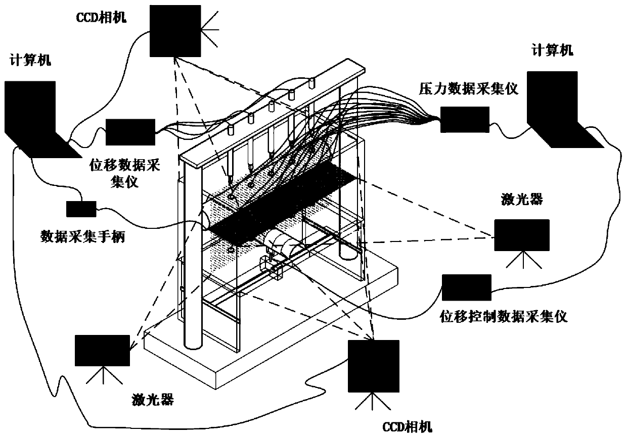
[0062] Picture 1-1 Shown is the overall three-dimensional schematic diagram of the model test device. The size of the model box is 700×300×400 (mm), and the outside is 20mm thick tempered glass, which contains a simulated stratum made of transparent soil. All simulated construction processes are carried out in the model box . The existing tunnel model is located at L above the longitudinal axis of the underpass construction. In this embodiment, the angle between the longitudinal axis of the tunnel and the longitudinal axis of the movable door in the horizontal space is 90°, that i...


PUM


Abstract

The invention discloses a visual test device for simulating shield underneath pass existing tunnel construction. The visual test device comprises a model box, an existing tunnel model, an adjusting system and a test process measuring system. A simulation stratum prepared from transparent soil is arranged in a model box, and all simulation construction processes are carried out in the model box. Existing tunnel models are simulated through polyethylene plastic pipes according to the elastic modulus similarity principle, model tunnels penetrate through the model box, and the two end faces of each tunnel are fixed to the two sides of the inner surface of the model box. The adjusting system is designed to be a sectional type movable door adjusting system. The test process measurement system iscomposed of six subsystems including a movable door displacement measurement control system, a soil body surface settlement measurement system, a soil body internal moving field measurement system, asoil pressure measurement system, a tunnel surface pressure distribution test system and a tunnel displacement measurement system. Data collected by each subsystem is provided for a computer PC for data analysis. The invention is used for researching the stratum disturbance action mechanism in the whole shield underneath pass construction process.

Description

technical field [0001] The invention belongs to the field of tunnel and underground engineering. Background technique [0002] With the rapid development of urban rail transit, the subway network has gradually formed and expanded, and a large number of new subway lines have begun to cross or pass through municipal pipelines and existing lines. attention from engineering and academia. Restricted by geological environment conditions and construction technology, shield tunneling of new tunnels will inevitably disturb the surrounding strata. Existing tunnels are prone to problems such as longitudinal uneven settlement, segment cracking, ballast bed disengagement, and joints under disturbance of the surrounding soil. Damage, water leakage and other problems endanger driving safety. However, the underpassing of the existing shield tunnel by shield tunneling is a complex system behavior involving multiple factors and multiple couplings and the complex interaction between structur...

Claims


Application Information

Patent Timeline
IPC IPC(8): G01N33/24G01L1/22G01B7/02G01B11/24G01N21/84
CPCG01B7/02G01B11/24G01L1/22G01N21/84G01N33/24
Inventor 吴遥杰赵昱宫全美周顺华田志尧李晖
Owner TONGJI UNIV
Why Eureka
Try Eureka